


Greensmaster 3320/3420Page 6 -- 54Electrical System
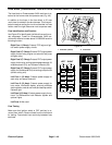
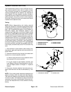
Backlap Switch
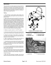
The backlap switch on Greensmaster TriFlex Hybrid
machines is used to control cutting reel backlap opera-
tion. The Toro Electronic Controller (TEC) uses the
backlap switch as an input to reverse cutting reel direc-
tion and also to prevent the cutting reels from raising
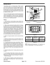
duringbacklapping. Thebacklap switchis locatedunder
the operator seat (Fig. 62).
The rear of the backlap switch should be depressed for
normal mow operation. When the front of the backlap
switch is depressed, the machine will be in backlap op-
eration. The indicator light on the switch identifies when
the machine is in backlap operation.
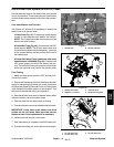
Testing
1. Park machine on level surface, lower cutting units,
stop engine, apply parking brake and remove key from
ignition switch.
2. Before disconnecting the backlap switch for testing,
the switch and circuit wiring should be tested as a TEC
electrical input using the Hand Held Diagnostic Display
(see Hand Held Diagnostic Display in the Troubleshoot-
ing section of this chapter). If input testing verifies that
the backlap switchand circuit wiring are functioning cor-
rectly,no furtherswitch testingis necessary. If,however,
input testing determines that the backlap switch and cir-
cuit wiring are not functioning correctly, proceed with
the following backlap switch testing procedure.
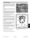
3. Raise and support operator seat to access backlap
switch.
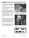
4. Make sure ignition switch is in the OFF position. Dis-
connectmachinewire harnesselectricalconnector from
the backlap switch.
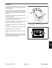
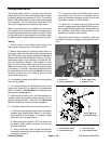
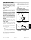
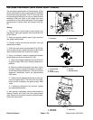
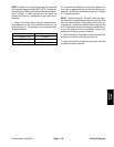
5. The backlap switch terminals are identified in Figure
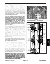
63 and the circuitry of the selector switch is shown in Fi-
gure 64.With the use of amultimeter (ohms setting),the
switch functions may be tested to determine whether
continuity exists between the various terminals for each
switch position. Verify continuity between switch termi-
nals.
6. Replace backlap switch if testing determines that it
is faulty.
7. If the backlap switch tests correctly and a circuit
problem still exists, check wire harness (see Electrical
Schematics and Wire Harness Drawings in Chapter 10
-- Foldout Drawings).
8. After testing is complete, connect machine wire har-
nessconnector to backlap switch. Lower and secure op-
erator seat.
1. Fuse block 2. Backlap switch
Figure 62
2
1
Figure 63
BACK OF SWITCH
SWITCH
POSITION
NORMAL
CIRCUITS
OTHER
CIRCUITS
MOW 2+1 5+4
BACKLAP 2+3 5+6
Figure 64
NOTE: Backlap switch terminals 1, 4, 5 and 6 are not
used on Greensmaster TriFlex Hybrid machines.