


Greensmaster 3320/3420Hydraulic System Page 5 -- 84
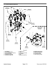
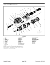
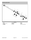
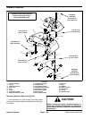
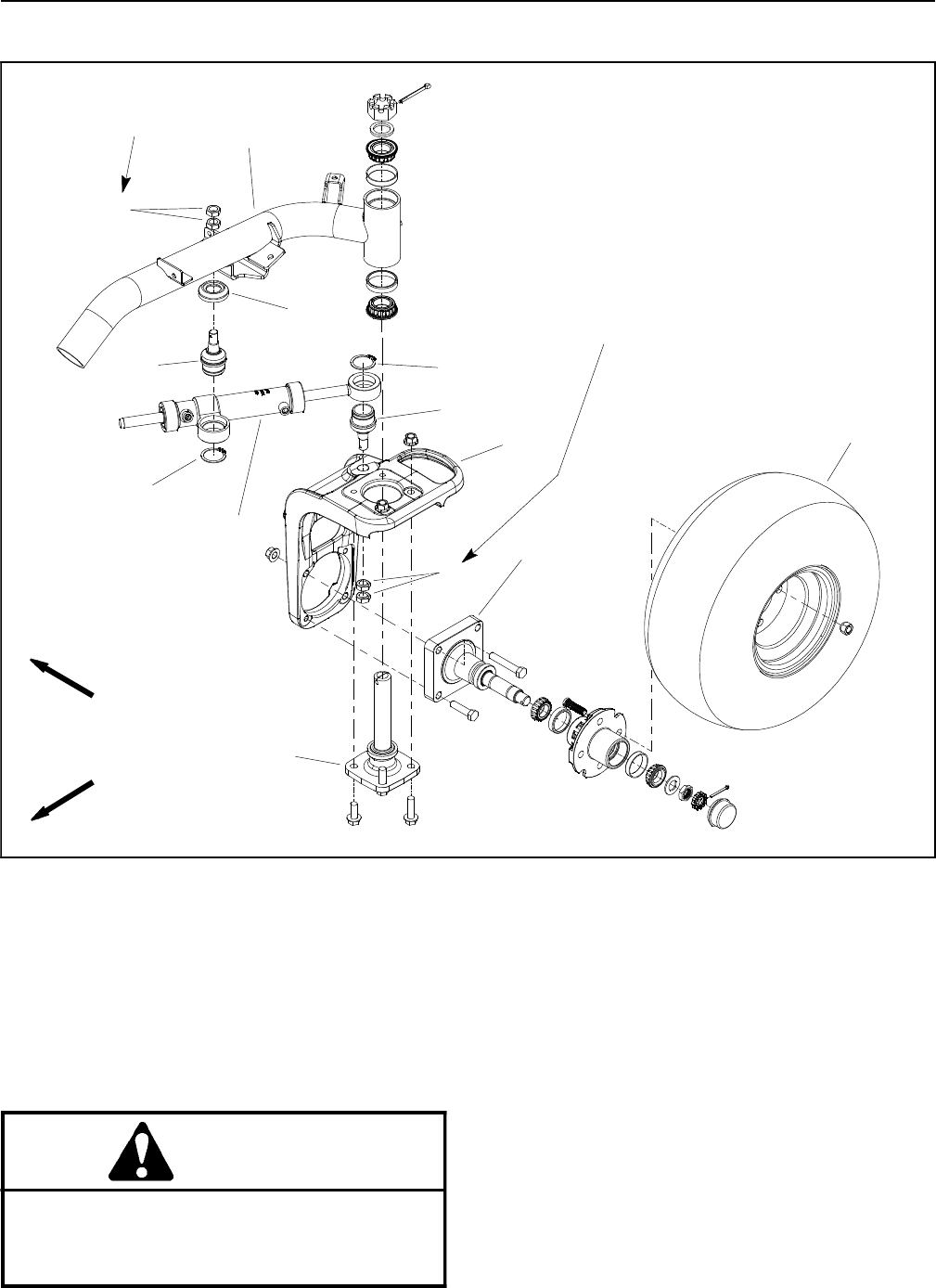
Steering Cylinder
1. Steering cylinder
2. Frame
3. Rear steering fork
4. Jam nut (4 used)
5. Rear wheel spindle
6. Steering spindle
7. Rear wheel assembly
8. Retaining ring (2 used)
9. Ball joint (2 used)
10. Cylinder spacer
Figure 56
FRONT
RIGHT
9
5
7
1
3
4
6
8
2
4
9
8
10
60 to 80 ft--lb
(82 to 108 N--m)
60 to 80 ft--lb
(82 to 108 N--m)
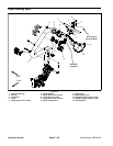
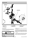
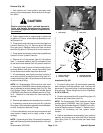
Removal (Fig. 56)
1. Parkmachine ona levelsurface, engagethe parking
brake, lower the cutting units and stop the engine. Re-
move key from the ignition switch.
CAUTION
Before continuing further, read and become fa-
miliar with General Precautions for Removing
and Installing Hydraulic System Components in
this section.
2. Operate all hydraulic controls to relieve hydraulic
system pressure.
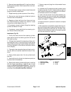
3. To allow easier access to steering cylinder,raise and
support tank mount plate assembly (hydraulic reservoir,
fuel tank and tank mount plate) (see Tank M ount Plate
Assembly in theService and Repairs section of Chapter
7 -- Chassis).
4. Labelsteering cylinder hydraulic hosesfor assembly
purposes. Thoroughly clean hydraulic hose ends prior
to disconnecting the hoses from steering cylinder.