


Greensmaster 3320 Page 3 -- 15 Gasoline Engine
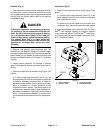
2. Disconnect battery cables from battery. Disconnect
negative battery cable first and positive cable last.
3. Close fuel shut--off valve on fuel tank.
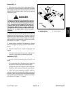
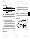
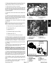
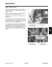
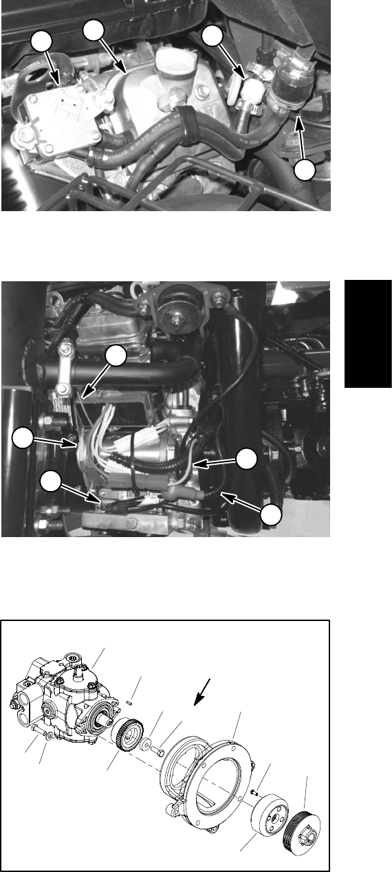
4. Disconnect fuel hoses from the fuel filter outlet and
thecheck valve near rear engine cylinder head (Fig.10).
Drain any fuel trapped in the fuel filter and fuel hose into
a suitable container.
5. Disconnect choke and throttle control cables from
engine.
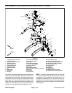
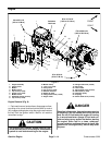
6. Loosen and remove cap screw (item 5), flat washer
(item 22), lock washer (item 20) and flange nut (item 6)
that secure wire harness ground connectors to engine
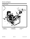
assembly (location shown in Fig. 11).
7. Disconnect wire harness connectors from engine
components:
NOTE: Before disconnecting wire harness connectors,
label all electrical leads for assembly purposes.
A. Alternator wire (from regulator/rectifier) (Fig. 11)
B. Fuel solenoid (Fig. 11)
C. Magneto (Fig. 11)
D. Oil pressure switch (next to oil filter)
E. Starter motor (Fig. 11)
F. Ground wire at rear muffler mount screw
8. Remove tension on generator belt and remove belt
from the generator pulley attached to engine crankshaft
(seeGeneratorBelt( Greensmaster 3320)in theService
and Repairs section of Chapter 6 -- Electrical System).
9. Support the engine assembly to prevent it from shift-
ing or falling.
10.Remove four (4) cap screws (item 13) that secure
engine assembly to pump mount (item 12).
IMPORTANT: Make sure to not damage the engine,
fuel lines, hydraulic hoses, electrical harness, con-
trolcablesor otherpartswhile removingthe engine.
11.Carefully move the engine assembly away from the
pump mount to slide the engine coupling/pulley off the
pump coupling (Fig. 12). Once the engine has cleared
the coupling, remove the engine from the machine.
12.If necessary, remove the coupling and generator
pulley from the engine crankshaft using Figure 9 a s a
guide.
13.If necessary, remove exhaust system components
from engine using Figure 9 as a guide.
Figure 10
1. Fuel filter
2. Check valve
3. Rear cylinder head
4. Fuel pump
2
1
3
4
Figure 11
1. Ground connectors
2. Alternator wire
3. Fuel solenoid
4. Magneto wire
5. Starter motor cable
4
1
2
5
3
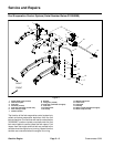
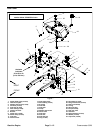
1. Piston pump
2. Cap screw (2 used)
3. Flat washer (2 used)
4. Coupling
5. Pump mount
6. Cap screw
7. Spacer
8. Screw (4 used)
9. Coupling
10. Generator drive pulley
11. Key
Figure 12
GREENSMASTER 3320
27 to 33 ft--lb
(37to44N--m)
7
3
8
1
10
9
2
5
6
4
11
Loctite #242
Gasoline
Engine