


Greensmaster 3320/3420 Hydraulic SystemPage 5 -- 53
4. Loosenthe four(4) cap screws thatsecure pump as-
sembly.
5. Remove pump from vise and remove fasteners.
6. Support thepumpassemblyand gently tap the pump
housing with a soft face hammer to loosen the pump
section. Be careful to not drop parts or disengage gear
mesh.
IMPORTANT: Mark the relative positions of the gear
teeth and the thrust plates so they can be as-
sembledin the same position.Do nottouch thegear
surfaces as residue on hands may be corrosive to
gear finish.
7. Remove the thrust plates and seals from pump. Be-
fore removing gear set, apply marking dye to mating
teeth to retain ”timing”.Pump efficiencymay be affected
if the teeth are not installed in the same position during
assembly.
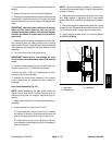
8. Turn front cover over, with seal side up.
IMPORTANT: Make sure to not damage the front
covercounterbore when removingthe seal fromthe
cover.
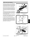
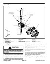
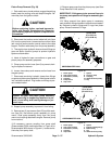
9. Carefully remove retaining ring and shaft seal from
the f ront cover (Fig. 37). Discard removed seal.
10.Clean all parts. Check all components for burrs,
scoring, nicks or other damage.
11.Replace the entire pump assembly if any internal
pump components are excessively worn, scored or
damaged.
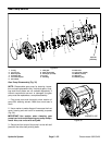
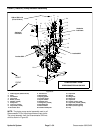
Gear Pu mp Assembly (Fig. 35)
NOTE: When assembling the gear pump, check the
markerlineonfrontcover,housingandendcoverto
make sure the parts are properly aligned during as-
sembly.
1. Apply clean hydraulic oil to all pump parts before as-
sembling.
2. Install new seal into front cover (Fig. 37):
A. Press shaft seal into front cover until it reaches
the bottom of the bore. Shaft seal should have the
seal lip and spring toward the inside of the pump.
B. Install retaining ring into the groove of the front
cover. Make sure that retaining ring is fully seated in
front cover groove.
NOTE: Pressure and back--up seals fit in grooves ma-
chinedintothrustplates.BodyO--ringsfit ingroovesma-
chined in housing.
3. Assemble pump components starting at front cover
end. Apply grease or petroleum jelly to new section
sealstoholdtheminpositionduringgearpumpassem-
bly.
4. Afterpump hasbeen assembled,tighten four(4) cap
screws by hand. Rotate thedrive shaftto check forbind-
ing. Protect the shaft if using a pliers to rotate shaft.
5. Torque the cap screws evenly in a crossing pattern
to 33 ft --lb (45 N--m).
1. Drive shaft
2. Retaining ring
3. Shaft seal
Figure 37
1
3
2
Hydraulic
System