


Greensmaster 3320/3420Page 6 -- 52Electrical System
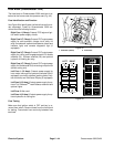
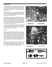
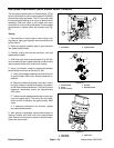
Parking Brake Switch
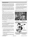
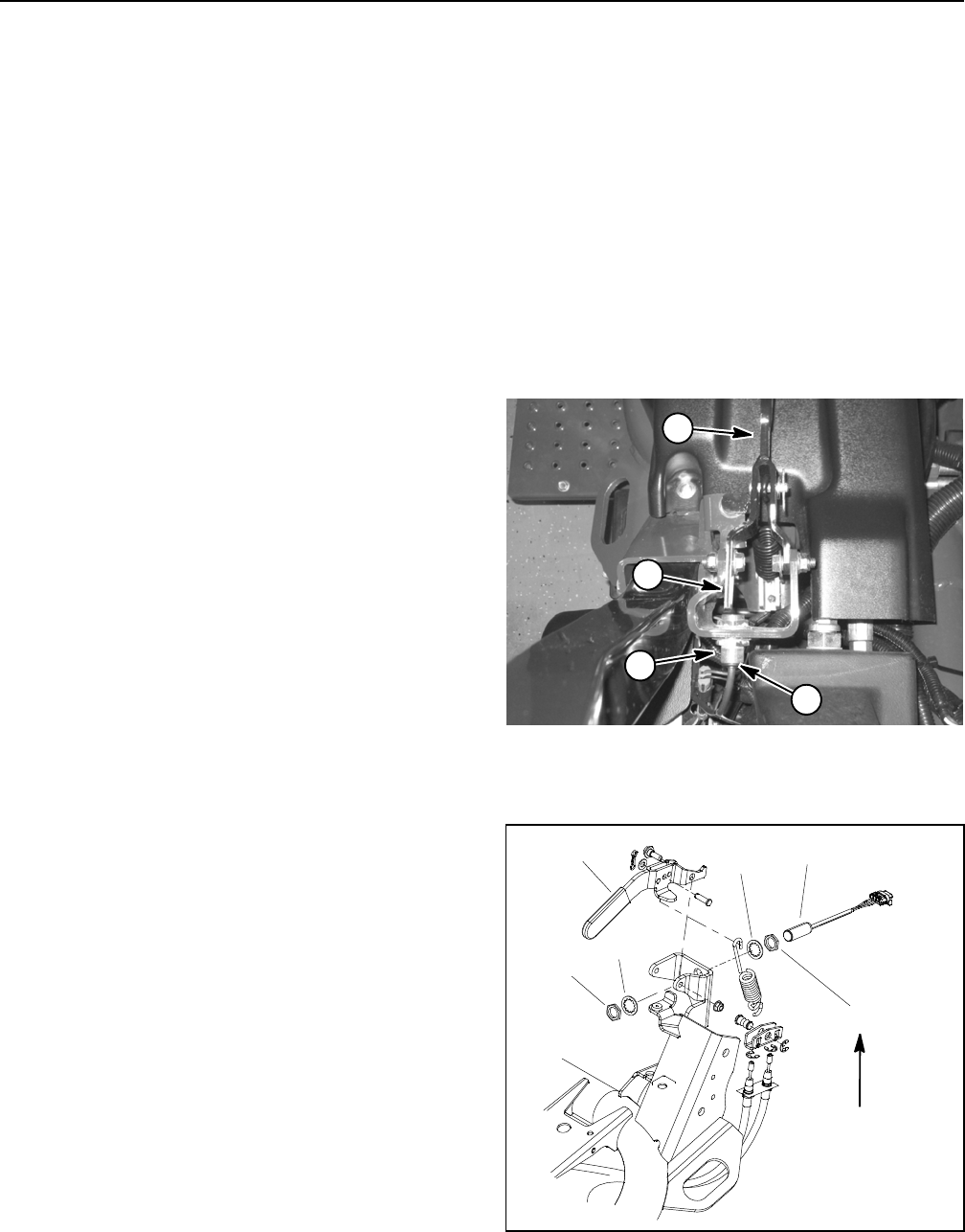
The parking brake switch is a normally open proximity
switch that mounts to the frame bracket used to attach
the parking brake lever assembly (Fig. 58). The sensing
plate for the brake switch is a tab on the parking brake
lever assembly. The Toro Electronic Controller (TEC)
monitors the operation of the parking brake switch.
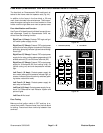
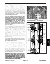
When the parking brake is not applied, the tab on the
parking brake lever is positioned near the target end of
theparkingbrakeswitchsotheswitchisclosed.Thetab
on the brake lever is moved away from the switch when
the parking brake is applied causing the switch to open.
Testing
1. Park machine on level surface, lower cutting units,
stop engine and remove key from ignition switch.
2. Before disconnecting the parking brake switch for
testing, the switch and its circuit wiring should be tested
asaTECelectricalinput usingthe HandHeldDiagnostic
Display (see Hand Held Diagnostic Display in the Trou-
bleshooting section of this chapter) or InfoCenter Dis-
play (see InfoCenter Display in this chapter). If input
testing verifies that the brake switch and circuit wiring
are functioning correctly, no further brake switch testing
is necessary. If, however, input testing determines that
the brake switch and circuit wiring are not functioning
correctly, proceed with the following parking brake
switch testing procedure.
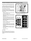
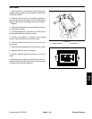
3. Locate parking brake switch. Make sure that parking
brake is not applied.
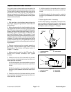
4. Turn ignition switch to the RUN position (do not start
engine) and check LED on cable end of parking brake
switch. The switch LEDshould be illuminated when the
parking b rake is not applied.
5. With the ignition switch still in the RUN position (do
not startengine), applyparking b rakeand check LEDon
cable end of brake switch. The switch LED should not
be illuminated when the parking brake is applied.
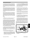
6. If the brake switch LED did not function correctly:
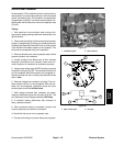
A. Make sure that parking brake switch is properly
adjusted (see Parking Brake Switch in the Adjust-
ments section of this chapter). If necessary, adjust
switchandreturntostep4above.
B. Make sure ignition switch is OFF and disconnect
the parking brake switch connector from the ma-
chine wire harness.
C. Using a multimeter, verify that the machine wire
harness connector terminal for black wire is closed
(continuity) to ground.
D. Turn ignition switch to the RUN position (do not
start engine) and verify with a multimeter that ma-
chine wire harness connector terminal for pink wire
has system voltage (12 VDC) present.
E. If black wire is closed to ground, pink wire has
system voltage presentand switch LED did notfunc -
tion, replace parking brake switch. Adjust switch af-
ter installation (see Parking Brake Switch in the
Adjustments s ection of this chapter).
7. After brake switch testing is complete, make sure
that switch connector is p lugged into machine wire har-
ness.
1. Brake lever
2. Parking brake switch
3. Switch LED location
4. Brake lever tab
Figure 58
2
1
3
4
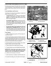
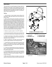
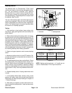
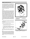
1. Parking brake switch
2. Parking brake lever
3. Jam nut (2 used)
4. Lock washer (2 used)
Figure 59
2
1
3
4
3
4
162 to 198 in--lb
(18.4to22.4N--m)