


Greensmaster 3320/3420Page 7 -- 8Chassis
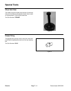
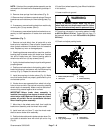
Brake Service
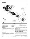
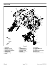
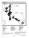
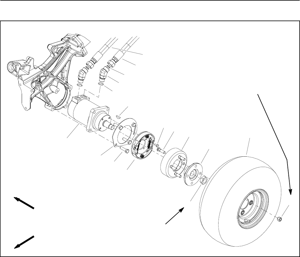
Figure 7
250 to 400 ft--lb
(339 to 542 N--m)
65 to 85 ft--lb
(89 to 115 N--m)
7
10
5
11
1
9
6
8
2
4
3
12
13
14
15
16
17
1. Wheel assembly
2. Wheel hub
3. Brake drum
4. Wheel stud (4 per wheel)
5. Brake assembly (LH shown)
6. Cap screw (4 per brake)
7. Lock nut
8. Cap screw (4 per motor)
9. Lug nut (4 per wheel)
10. Brake lever tab
11. Hydraulic motor (LH shown)
12. Woodruff key
13. Hydraulic hose
14. Hydraulic hose
15. O--ring
16. 45
o
hydraulic fitting (2 per motor)
17. O--ring
FRONT
RIGHT
Removal (Fig. 7)
1. Park machine on a level surface, lower the cutting
units and stop the engine. Remove key from the ignition
switch.
2. Chock wheels to prevent machine from shifting.
3. Loosen, but do not remove, lock nut (item 7) from
wheel motor shaft.
4. Remove front wheel assembly (see Wheel Removal
in this section). Make sure to support machine with jack
stands.
5. Make sure parking brake is disengaged.
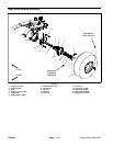
6. Remove e--ring and clevis pin that secure brake
cable to brake actuator lever. Position brake cable end
away fr om lever (Fig. 8).
IMPORTANT: DO NOT hit brake drum assembly,
puller or wheel motor with a hammer during drum
assembly removal or installation. Hammering may
cause damage to the wheel motor.
7. Make sure that lock nut on wheel motor shaft is loos-
ened at least two (2) turns. Use hub puller (see Special
Tools) to loosen brake drum assembly from motor.
8. Removelocknutand brake drumassembly frommo-
tor shaft. Discard lock nut. Locate and retrieve woodruff
key.