


Rev. A
Greensmaster 3320/3420
DPA Cutting Units
Page 8 - 25
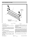
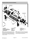
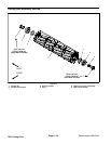
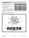
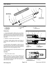
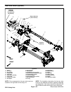
Disassembly of Cu tting Reel (Fig. 24)
1. Remove bearing lock screw (item 5) and reel nut
(item 6) from cutting reel. Reel nut has LH threads and
is in end of reel shaft identified with a groove that is just
inside of reel spider (Fig. 25).
2. Slide bearings from reel shaft.
IMPORTANT: The reel shaft bearing journals are
painted. Proper bearing fiton thereel shaftincludes
having the paint on theshaft to ensure correct bear-
ing clearance. DO NOT remove paint from the reel
shaft bearing journals when servicing the cutting
reel.
3. Note orientation of flocked seals for assembly pur-
poses. Remove seals from reel shaft.
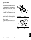
Inspection of Cutting Reel (Fig. 24)
1. Inspect reel bearings to insure that they spin freely
and have minimal axial play.
2. Inspectthe reel shaftas follows. If reel damage isde-
tected, replace reel.
A. Check the reel shaft for bending and distortion by
placing the shaft ends in V- blocks.
B. Check the reel blades for bending or cracking.
C. Check the service limit of the reel diameter (see
Preparing a Reel for Grinding in this section).
D. Check threads in ends of reel shaft.
3. Check the splines in the reel nut (item 6) for exces-
sive wearor distortion. Replace reelnutif damageis evi-
dent.
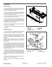
Assembly of Cutting Reel (Fig. 24)
1. If bearings and/or flocked seals were removed from
reel shaft, discard removed components and replace.
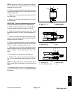
IMPORTANT: The flocked seal should be installed
so the flocked side of the seal is toward the bearing
location.
2. Slide flocked seals ( flocked side orientated toward
bearing location) and bearings fully onto reel shaft.
Bearings and seals should bottom on reel shaft shoul-
der.
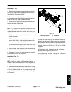
3. Install bearing lock screw (item 5) and reel nut (item
6) into reel shaft to secure bearings. Reel nut has LH
threads andshould be installed in end ofreel shaft iden-
tified with a groove that is just inside of reel spider (Fig.
25).
NOTE: Installation torque for bearing lock screw and
reel nut is from 90 to 110 ft- lb (123 to 149 N- m).Itis
easiest to torque these items after the cutting reel is
installed in the cutting unit frame (see Reel Assembly
Removal and Installation in this section).
4. Thoroughly fill spline area of reel nut (left side of cut-
ting reel) with grease.
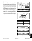
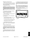
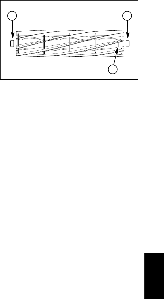
1. LH threads
2. Groove
3. RH threads
Figure 25
1
2
3
DPA Cutting
Units