


Greensmaster 3320/3420 Page 6 -- 57 Electrical System
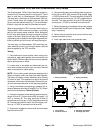
Toro Electronic Controller (TEC)
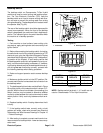
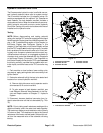
GreensmasterTriFlexHybridmachines use aToro E lec-
tronic Controller (TEC) to monitor the condition of vari-
ous switches (inputs) and then direct electrical power
output to allowcertain machinefunctions.The controller
is attached to the frame under the operator seat (Fig.
70). TEC inputs and outputs on your Greensmaster can
be checked with the Hand Held Diagnostic Display (see
Hand Held Diagnostic Display in the Troubleshooting
section of t his chapter) or InfoCenter Display (see
InfoCenter Display in this chapter).
Inputs from the ignition, neutral, parking brake, seat,
joystick, mow, backlap and engine oil pressure are all
monitored by the TEC controller. TEC inputs on Green-
smaster 3420 machines also include the alternator, en-
gine temperature sender and optional hydraulic
temperature sender (if equipped). TEC inputs on
Greensmaster 3320 machines also include the leak de-
tector sensor if equipped with the optional Turf Defen-
der
TM
Leak Detector.
On all Greensmaster TriFlex Hybrid machines, TEC
controller current output to the lift circuit hydraulic valve
solenoidcoils (S1, S2,S3 and S4)and console diagnos-
tic light (if equipped) are controlled based on the inputs
received by the controller. TEC outputs on Greensmas-
ter 3320 machines also include the start solenoid, fuel
solenoid, charge circuit relay, kill relay and optional Turf
Defender
TM
Leak Detector indicator light and alarm.
TEC outputs on Greensmaster 3420 machines also in-
clude the start relay, glow relay, fuel pump, engine run
solenoid (hold coil), fan relay and console indicator
lights (if equipped).
If the controller detects a malfunction in any of the con-
trolled circuits, the diagnostic light or InfoCenter Display
canbeusedtoidentifythefault.
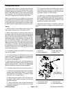
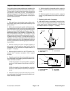
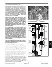
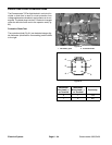
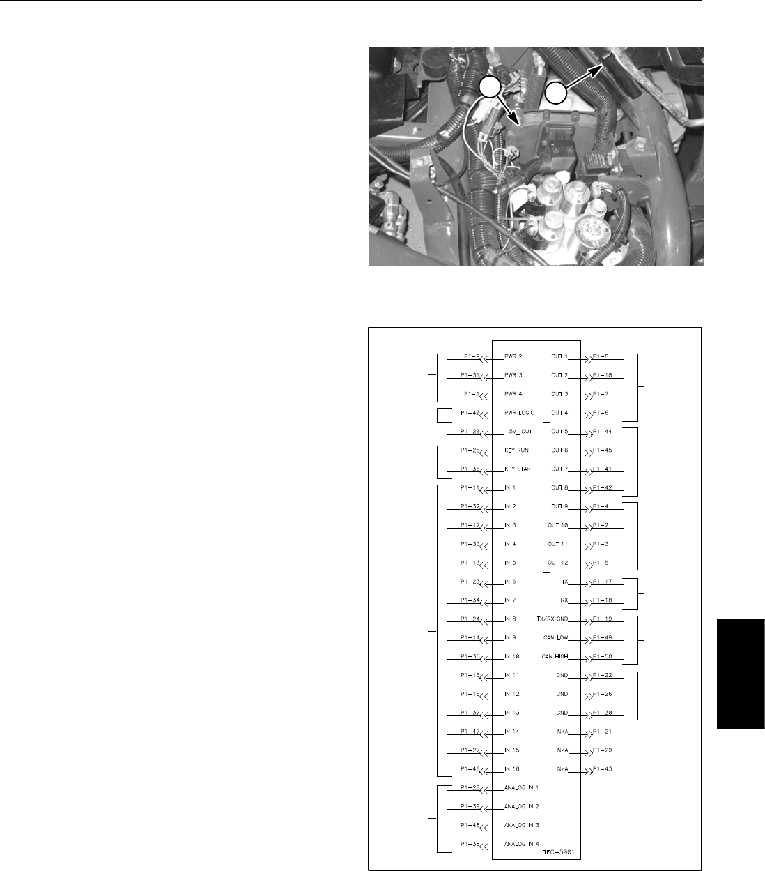
The diagram in Figure 71 depicts the connection termi-
nal functions of the T EC controller. A fifty (50) pin wire
harness connector attaches to the controller. The con-
nector pins are listed in the diagram. Note that electrical
powerforcontroller outputsis providedthroughthree(3)
connectors each protected with a 7.5 amp fuse.
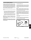
Because of the solid state circuitry built into the control-
ler, there is no method to test it directly. The controller
may be damaged if an attempt is made to test it with an
electrical test device, such as a digital multimeter.
IMPORTANT: Before welding on the machine, dis-
connect both battery cables from the battery, dis-
connect the wire harness connector from the TEC
controller and disconnect the terminal connector
from the alternator. This will prevent damage to the
electrical system of your Greensmaster.
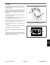
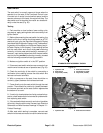
Figure 70
1
1. TEC controller location 2. Seat platform
2
Figure 71
12V POWER
(7.5AFUSES)
12VLOGIC
IGNITION
SWITCH
INPUTS
DIGITAL
INPUTS
(OPEN/
ANALOG
INPUTS
POWER
(2AMPFUSE)
DIAGNOSTIC
DISPLAY
CANBUS
CLOSED)
OUTPUTS
(PWR2)
GROUND
(VARIABLE)
OUTPUTS
(PWR3)
OUTPUTS
(PWR4)
Electrical
System