


Greensmaster 3320/3420
DPA Cutting Units
Page 8 -- 20
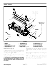
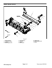
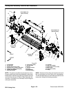
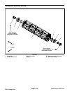
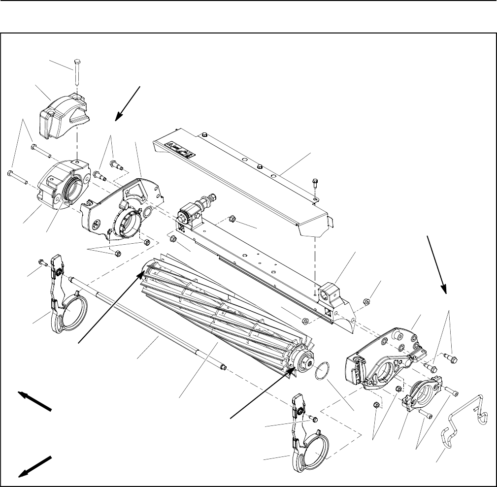
Cutting Reel Assembly Removal a nd Installation
1. Crossmember
2. LH side plate
3. Washer head screw (2 used)
4. Shoulder bolt (2 used per side plate)
5. Flange nut (2 used per side plate)
6. Cutting reel assembly
7. Pitch arm (2 used)
8. Cap screw (2 used)
9. RH side plate
10. Weight
11. Hex nut (4 used)
12. O--ring
13. Grass shield
14. Flat wire spring
15. Crosslink
16. Reel motor adapter
17. Socket head screw (2 used)
18. Motor clamp
19. Cap screw (2 used)
20. Weight
Figure 22
FRONT
RIGHT
Grease OD
210 to 240 in--lb
(24to27N--m)
4
2
9
5
13
1
4
5
5
5
7
15
3
7
11
3
210 to 240 in--lb
(24 to 27 N--m)
surface
Grease OD
surface
6
14
16
18
11
17
8
10
12
19
20
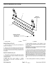
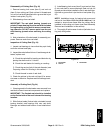
NOTE: This section provides the procedure for remov-
ing and installing the cutting reel assembly (cutting reel,
flockedseals,reel bearings,bearinglock screwand reel
nut) from the cutting unit. Refer to Reel Assembly Ser-
vice later in this section for information on servicing the
cutting reel assembly.
NOTE: Removal of the cutting reel requires removal of
the LH side plate from the cutting unit crossmember.
The RH side plate does nothave to beremovedfrom the
frame when using the following procedure.