


Greensmaster 3320/3420
DPA Cutting Units
Page 8 -- 17
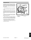
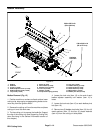
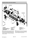
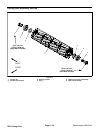
Removal (Fig. 17)
1. Remove lock nut (item 3), compression spring (item
2) and washer (item 11) from bedbar adjuster screw.
2. Remove bedbar (see Bedbar Removal in this sec-
tion).
NOTE: Bedbar adjuster shaft (item 4) has left--hand
threads.
3. Unscrewbedbaradjuster shaft (item4)from thebed-
bar adjuster screw.
4. Remove retaining ring (item 9) and wave washer
(item 8) from adjuster shaft and remove adjuster shaft
from cutting unit frame.
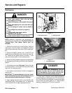
5. Inspect flange bushings (item 5) in cutting unit side
plate and remove if necessary.
6. If detent (item 7) is damaged, remove it from cutting
unit side plate by removing the cap screw (item 6).
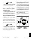
Installation (Fig. 17)
1. If detent (item 7) was removed, secure detent to cut-
ting unit side plate with cap screw.
2. If flange bushings (item 5) were removed, align key
onbushingtoslotinframeandinstallbushings.
3. Slide adjuster shaft (item 4) into flange bushings in
cutting unit side plate. Secure adjuster shaft with wave
washer (item 8) and retaining ring (item 9).
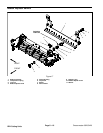
NOTE: Bedbar adjuster shaft (item 4) has left --hand
threads.
4. Apply antiseizelubricant tothreadsof bedbaradjust-
er screw that fit into adjuster shaft. Thread bedbar ad -
juster screw (item 10) into adjuster shaft.
5. Install bedbar (see Bedbar Installation in this sec-
tion).
6. Install washer (item 11), spring (item 2) and lock nut
(item 3) onto adjuster screw. Tighten the lock nut on
each bedbar adjuster assembly until the compression
spring is fully compressed,then loosen locknut 1/2 turn.
7. Adjust cutting unit (see Cutting Unit Operator’s
Manual).
DPA Cutting
Units