


Rev. A
Greensmaster 3320/3420Page 6 - 70Electrical System
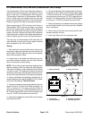
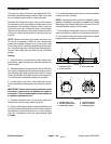
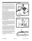
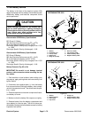
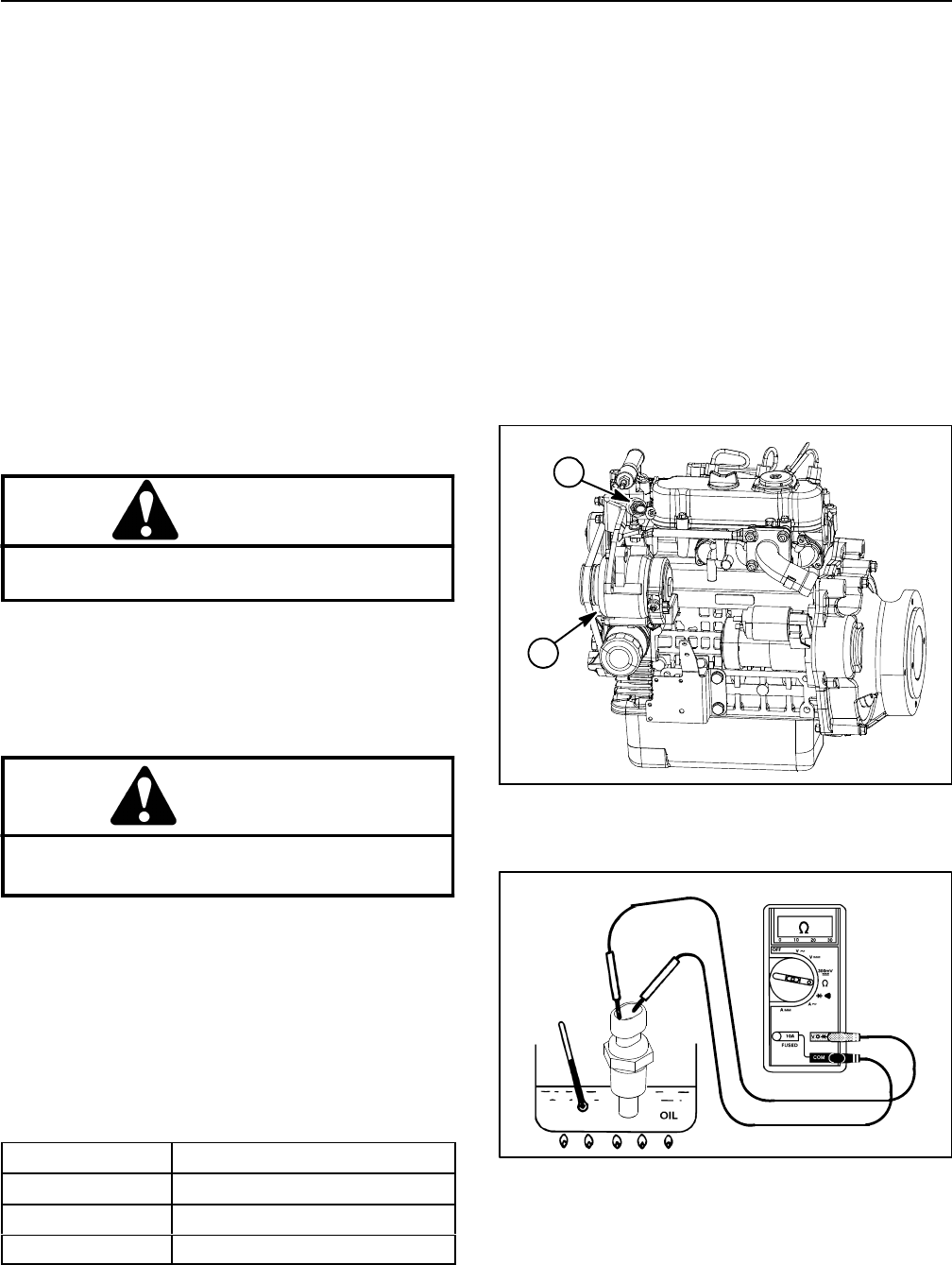
Temperature Sender (Greensmaster 3420)
The temperature sender is located near the alternator
on thewater flange attachedto the engine cylinderhead
(Fig. 91).
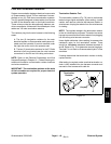
The resistance of the temperature sender reduces as
the engine coolant temperature increases. The chang-
ing resistance of the temperature sender signals the
console temperature gauge to indicate engine coolant
temperature during machine operation.
Temperature Sender Test
1. Park machine on a level surface, lower cutting units,
stop engine, apply parking brake and remove key from
ignition switch.
2. Locate temperature sender on engine and discon-
nect wire harness connector from sender.
CAUTION
Make sure engine is cool before removing the
temperature sender from engine.
3. Lower coolant level in the engine and remove the
temperature sender from water flange.
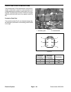
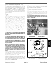
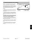
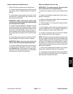
4. Put sender in a container of oil with a thermometer
and slowly heat the oil (Fig. 92).
CAUTION
Handle the hot oil with extreme care to prevent
personal injury or fire.
NOTE: Prior to taking resistance readings with a digital
multim eter, short themeter testleads together.The me-
ter will display a small resistance value (usually 0.5
ohms or less) due to the internal resistance of the meter
and test leads. Subtract this value from from the m ea-
sured value of the component you are testing.
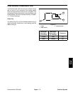
5. Check resistance of the sender with a multimeter
(ohms setting) as the oil temperature increases.
OIL TEMP
TEMP SENDER RESISTANCE
68
o
F(20
o
C) 11.4 to 13.6 10K ohms
140
o
F(60
o
C) 2.3to2.610Kohms
212
o
F (100
o
C) 0.6to0.710Kohms
6. Replacetemperature senderif specifications are not
met.
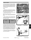
7. Install temperature sender to the water flange.
A. Clean threads of water flange and temperature
sender thoroughly. Apply thread sealant to the
threads of the sender.
B. Screwsender into the waterflange until itis finger
tight. Then, tighten sender an a dditional 2 to 3 full
turns.
C. Connect wire harness connector to sender.
8. Fill engine cooling system.
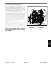
Figure 91
1. Temperature sender 2. Alternator
2
1
Figure 92