


Greensmaster 3320/3420 Page 6 -- 99 Electrical System
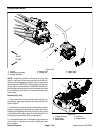
7. Remove motorcover and wave washer (item 4) from
rotor assembly. Remove and discard O--rings (items 14
and 3) from cover.
8. Remove and discard O--ring (item 8) from motor
housing.
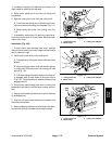
IMPORTANT: Make sure to not damage the gearbox
cover counter bore when removing the shaft seal
from the cover.
9. Carefullyremove shaftseal from gearbox cover.Dis-
card removed seal.
10.If necessary, remove bearings from output gear
(item11)and rotor(item 6).Discard bearingsifremoved.
11.Inspect grease in output gear area ofmotor housing.
If grease is clean and not contaminated, it can remain in
housing. If grease is contaminated, clean grease from
housing and replace with 15ml of NLGI grade 00 grease
during motor assembly.
12.Inspect cutting reel motor components for wear or
damage. Replace components or cutting unit motor as-
sembly if necessary.
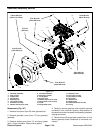
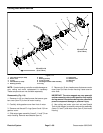
Assembly (Fig. 114)
1. Make sure that motor components are cleaned be-
fore assembly.
2. If bearings were removed from output gear (item 11)
or rotor (item 6) install new bearings. Make sure that
bearings are fully pressed onto shafts.
3. Lubricatenew inner O--ring (item8) with dielectric lu-
bricant (see Special Tools in this chapter) and install O--
ring into groove in motor housing.
IMPORTANT: The rotor magnets are very powerful
and cancausethe rotorto shift positionveryrapidly
during installation. Be cautious during rotor install-
ation to prevent component damage or personal in-
jury.
4. Use cutting reel motor rotor tool set (see Special
Tools in this chapter) to carefully install rotor assembly
(items 5, 6 and 7) into motor h ousing.
5. Lubricate new O--rings (items 14 and 3) with dielec-
tric lubricant (see Special To ols in this chapter) and
install O--rings to grooves in motor c over. Place wave
washer (item 4) in cover.
6. Carefullyslide motor cover ontorotor until it contacts
motor housing. Secure cover with six (6) torx head
screws.
7. Make sure that rotor rotates before continuing with
motor assembly.
8. Placewave washer(item 4) intohousingbore forout-
put gear bearing.
9. Make sure that output gear area of motor housing
has clean grease remaining in housing. If grease was
cleaned from housing, install 15ml of new NLGI grade
00 grease into housing during motor assembly.
10.Slide output gear assembly (items 5, 11 and 7) into
front of housing. Make sure that output gear teeth mesh
with rotor gear.
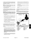
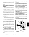
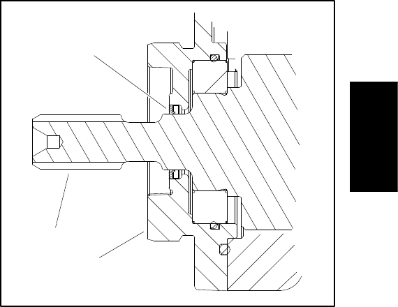
11.Install shaft seal (item 13) into gearbox cover. Press
shaft seal into front cover until it is flush with the cover
surface. Shaft seal should have the seal lip toward the
inside of the motor (Fig. 115).
12.Lubricate new O--rings (items 8 and 10) with dielec-
tric lubricant (see Special Tools in this chapter) and
install O--rings to grooves in gearbox cover.
IMPORTANT: Make sure to not damage the shaft
seal when installing the gearbox cover.
13.Carefully slide gearbox cover onto output gear shaft
until it contacts motor housing. Secure cover with six (6)
torx head screws.
14.Torque all torx screws (item 1) on gearbox cover and
motor cover from 35 to 45 in--lb (4 to 5 N--m).
1. Output gear
2. Gearbox cover
3. Shaft seal
Figure 115
3
2
1
Electrical
System