


Greensmaster 3320/3420 Hydraulic SystemPage 5 -- 95
NOTE: The Turf Guardian
TM
Leak Detector System is
optional on Greensmaster TriFlex Hybrid machines.
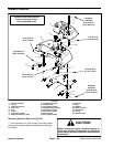
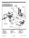
Removal (Fig. 63)
1. Park machine on a level surface, set brake, lower
cutting unitsand stop engine. Removekey from theigni-
tion switch.
CAUTION
Before continuing further, read and become fa-
miliar with General Precautions for Removing
and Installing Hydraulic System Components in
this section.
2. Remove leak detector tank (see Leak Detector Tank
in this section).
3. Clean junction of tank hose (item 22) at solenoid
valve fitting (item 21). Loosen hose clamp (item 19) and
disconnect tank hose at solenoid valve fitting.
4. Unplug machine wire harness connector from the
solenoid valve connector.
5. Removetwo (2)cap screws (item23) and lock wash-
ers (item 24) that secure solenoid valve assembly to hy-
draulic reservoir.
6. Remove solenoid valve assembly from machine.
7. If necessary, remove fittings from solenoid valve
manifold. Discard removed O--rings.
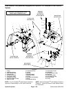
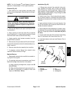
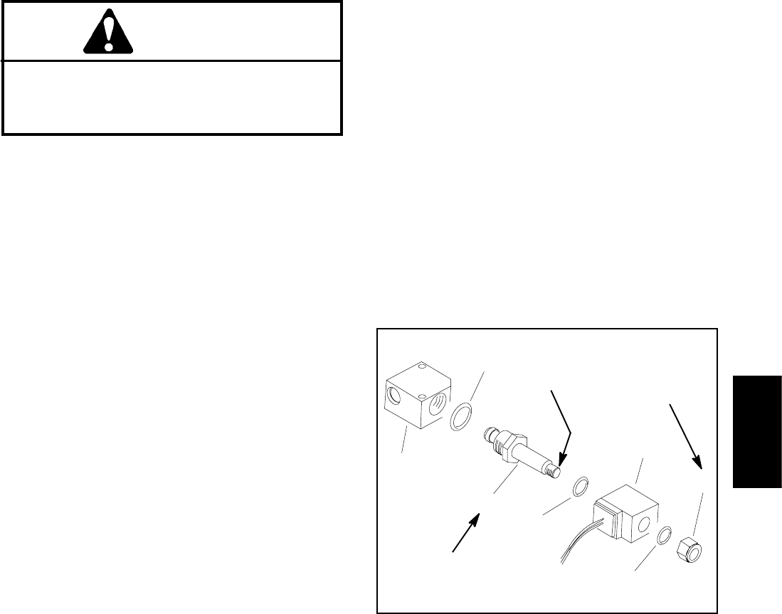
Manifold Service
1. Disassemble solenoid valve manifold as needed us-
ingFigure64asaguide.
2. For cartridge valve service procedures, see Control
Manifold Cartridge Valve Service in this section.
A. When installing cartridge valve, torque valve 35
ft--lb (47 N --m).
B. Wheninstalling solenoidcoil, applya dropof Loc-
tite #242 (or equivalent) to threads of valve and
torque nut 10 in--lb (1.1 N--m).
Installation (Fig. 63)
1. If fittings were removed from solenoid valve man-
ifold, lubricate and place new O--rings onto fittings.
Install fittings into manifold openings. Tighten fittings
(see Hydraulic Fitting Inst allation in the General Infor-
mation section of this chapter). Torque fittings from 40
to 50 ft--lb (55 to 67 N--m).
2. Position cover (item 17) and solenoid valve assem-
bly to hydraulic reservoir. Orientate the solenoid valve
assembly so the solenoid coil is closer to the front of the
reservoir.
3. Apply antiseize lubricant to t he end t hreads of the
two (2) cap screws used to secure solenoid valve as-
sembly to hydraulic reservoir.
4. Secure solenoid valve assembly to hydraulic reser-
voir with two (2) cap screws (item 23) and lock washers
(item 24). Torque capscrews from 30 to60 in--lb (3.4 to
6.7 N--m).
5. Connect tank hose (item 22) to solenoid valve fitting
(item21)andsecurewithhoseclamp(item19).
6. Install leak detector tank (see Leak Detector Tank in
this section).
1. Manifold
2. Cartridge valve
3. Seal
4. Nut
5. Solenoid coil
6. Cartridge seal
Figure 64
2
3
4
1
5
6
10 in --lb
(1.1 N--m)
3
35 ft--lb
(47 N--m)
Loctite #242
Hydraulic
System