


Greensmaster 3320/3420 Page 7 -- 17 Chassis
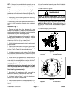
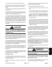
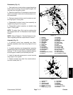
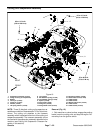
Disassembly (Fig. 13)
1. Parkmachine on alevel surface,engage theparking
brake, lower the cutting units and stop the engine. Re-
move key from the ignition switch.
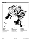
2. Remove screws (item 12) that secure console cover
(item 2) to console. Lower cover to allow access to con-
sole components.
3. Remove components from control console as need-
ed using Figure 13 as a guide.
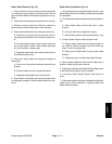
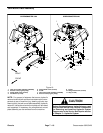
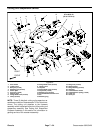
4. Disassemble functional control lever assembly as
needed using Figure 14 as a guide.
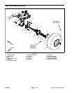
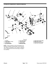
5. Disassemble joystick assembly as needed using
Figure 15 as a guide.
NOTE: The alarm (item 15) is used on machines that
are equipped with the Turf Guardian
TM
Leak Detector
System.
NOTE: Refer to Chapter 6 -- Electrical System for infor-
mation regarding electrical components on console.
Assembly (Fig. 13)
1. If functional control lever assembly was disas-
sembled, assemble control lever using Figure 14 as a
guide.
2. If joystick assembly was disassembled, assemble
joystickusingFigure 15as aguide. Iffinger springwash-
ers (item 7 in Fig. 15) were removed, position washers
so that fingers on washer point towards pivot hub.
3. Install all removed components to control console
using Figure 13 as a guide.
4. Position console cover (item 2) to console and se-
cure with screws (item 12).
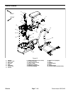
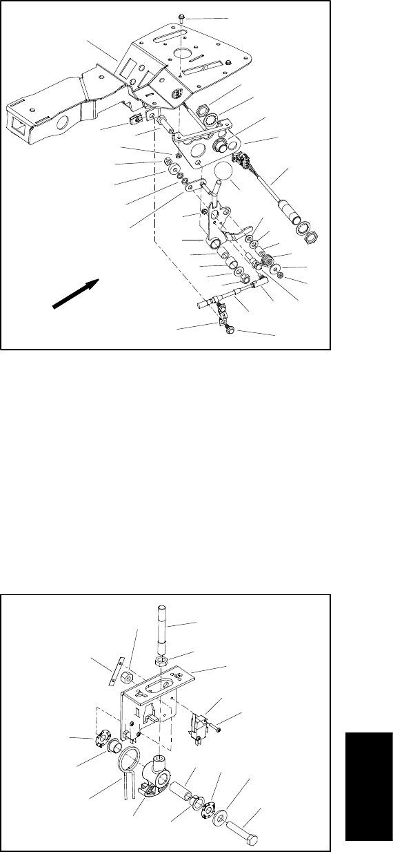
1. Console
2. Pivot tube
3. Functional lever
4. Split bushing
5. Cap screw
6. Flat washer
7. Lock nut
8. Roller pivot
9. Bushing
10. Flat washer
11. Spring spacer
12. T orsion spring
13. Flat washer
14. Lock nut
15. Bearing spacer (2 used)
16. Bearing
17. Lock nut
18. Spring pin
19. Ball joint
20. Neutral lock cable
21. Lock nut
22. Cable clamp
23. Neutral switch
24. Knob
25. Mow switch
26. Screw (2 used)
27. Screw (2 used)
28. Lock nut (2 use d)
29. Clip (2 used)
30. Lever bracket
31. Jam nut (4 used)
32. Lock washer (4 used)
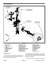
Figure 14
2
3
4
5
6
7
8
9
10
11
12
13
14
16
17
18
19
20
21
22
24
27
28
26
29
23
15
1
25
30
31
32
FRONT
1. Joystick rod
2. Jam nut
3. Joystick bracket
4. Switch (2 used)
5. Screw (2 per switch)
6. Spacer
7. Finger spring washer
8. Flat washer
9. Cap screw
10. Bushing
11. Pivot hub
12. Torsion spring
13. Speed nut (2 used)
14. Lock nut
Figure 15
2
3
6
8
9
10
11
13
1
5
7
12
14
4
7
10
Chassis