


Greensmaster 3320/3420 Page 6 -- 39 Electrical System
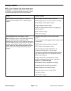
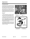
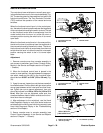
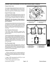
Neutral and Mow Switches
The neutral and mow switches are normally open prox-
imity switches that mount to the console assembly (Fig.
32). The sensing plate for these switches is a tab on the
functional control lever. The Toro Electronic Controller
(TEC) m onitors the operation of the neutral and mow
switches.
When the functional control lever is in the neutral posi-
tion, thetabonthe leveris positionednearthe targetend
of the neutralswitch causing the switchto close. Thetab
on the functional control lever is moved away from the
neutral switch when the lever is in either the mow or
transport position causing the switch to be in its normal
open state.
When the functional control lever is in the mow position,
the tab on the lever is positioned near the target end of
the mow switch causing the switch to close. The tab on
the functional control leveris movedaway fromthe mow
switch when the lever is in either the neutral ortransport
position causing the switch to be in its normal open
state.
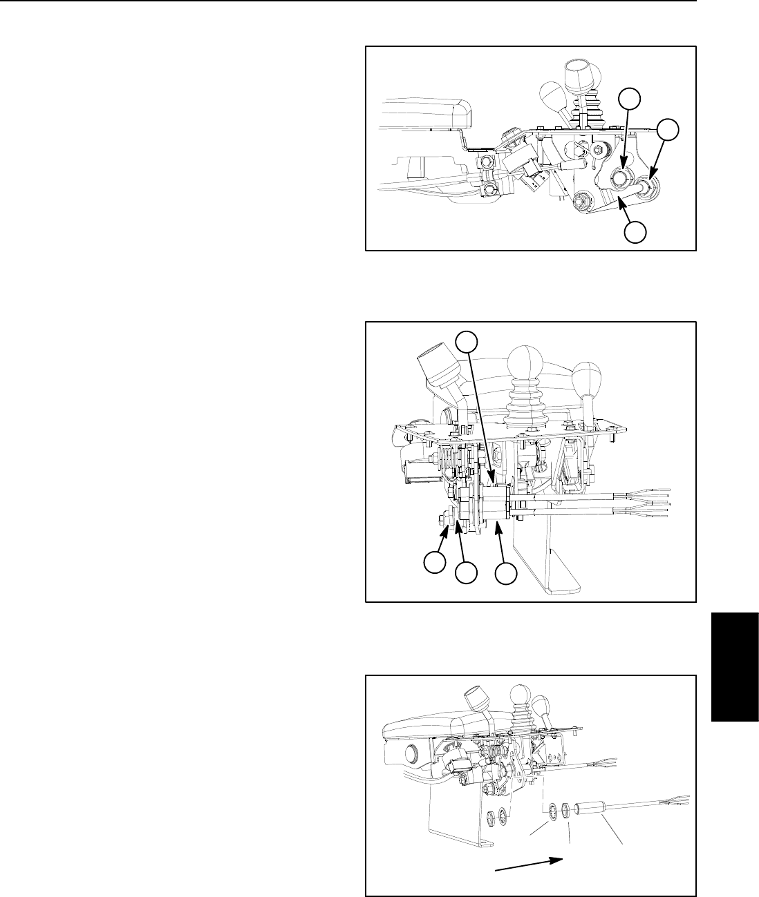
Adjustment
1. Remove console cover from console assembly to
gain access to switches (see Control Console Disas-
sembly in the Service and Repairs section of Chapter 7
-- Chassis).
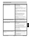
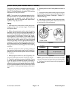
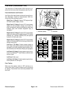
2. When the functional control lever is placed in the
neutral or mow position, the gap between the appropri-
ate switch head and the tab on the functional lever
should be from 0.090” to 0.120” (2.3 to 3.0 mm) (Fig.
33).
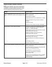
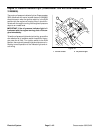
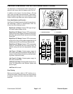
3. Ifgap isincorrect, loosenjam nutsthat secure switch
toconsole bracket.Position switch withjam nutstoallow
correct gap between switch head and functional lever
tab. Tighten jam nuts to secure adjustment. Jam nuts
should be torqued from 162 to 198 in--lb (18.4 to 22.4
N--m). After jam nuts are tightened, make sure that
clearance between head of switch and tab on the func-
tional lever has not changed.
4. After adjustment to the switch(es), use the Hand
Held Diagnostic Display to verify that neutral and mow
switchesand circuit wiring arefunctioning correctly(see
Hand Held Diagnostic Display in the Troubleshooting
section of this chapter).
5. Secure console cover to console assembly (see
Control Console Assembly in the Service and Repairs
section of Chapter 7 -- Chassis).
1. Functional lever tab
2. Mow switch
3. Neutral switch
Figure 32
2
1
3
1. Functional lever tab
2. Mow switch
3. Neutral switch
4. Gap
Figure 33
2
1
3
4
1. Switch (mow shown)
2. Jam nut (2 used)
3. Lock washer (2 used)
Figure 34
162 to 198 in--lb
(18.4 to 22.4 N--m)
2
1
3
Electrical
System