


Greensmaster 3420 Page 4 -- 13 Diesel Engine
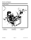
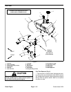
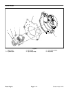
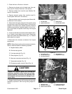
Radiator Removal (Fig. 8)
1. Park machine on a level surface, lower the cutting
units, stop the engine, engage parking brake and re-
move the key from the ignition switch.
CAUTION
DO NOT open radiator cap or drain coolant if the
engine orradiatoris hot.Pressurizedhot coolant
can escape and cause burns.
Ethylene--gycol antifreeze is poisonous. Dis-
pose ofit properly orstore itin aproperly labeled
container away from children and pets.
2. Remove the radiator cap.
3. Drain radiator into a suitable container by discon-
necting lower radiator hose (item 21) from the radiator.
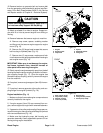
4. Remove screen ( item 15) from radiator shroud.
5. Remove four (4) flange head screws (item 16) that
secure radiator shroud (item 2) to radiator assembly.
Remove radiator shroud.
6. Remove flange head screw that secures R--clamp
(item 14) to bottom of front shroud (item 19).
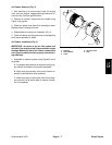
7. Remove the f ollowing hoses from the radiator:
A. Loosen hose clamps and disconnect breather
hose (item 24) and overflow hose (item 23) from ra-
diator filler neck.
B. Loosen hose clamp (item 6) and disconnect up-
per radiator hose (item 22).
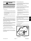
8. Locate splice fitting in fuel return hose near fuel
pump. Disconnect one of the return hose sections from
splicefittingand removereturn hosefrom bothr--clamps
(item 7) on f ront shroud (item 19).
9. Remove flange head screw and flange nut that se-
cure fuel pump assembly to front shroud. Position fuel
pump assembly away from radiator assembly.
10.Disconnect fan wire connector from machine wire
harness.
11.Support radiator assembly to prevent it from falling.
12.Remove four (4) flange nuts that secure frontshroud
to machine. Remove radiator assembly from machine.
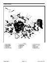
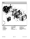
13.Remove componentsfrom radiatoras necessary us-
ing Figure 8 as a guide.
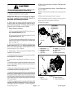
Radiator Installation (Fig. 8)
1. Assemble all removed components to radiator using
Figure 8 as a guide.
2. Position radiator assembly to machine. Secure front
shroudtomachinewithfour(4)flangenuts.
3. Position fuel pump assembly to radiator assembly
andsecurewithflangeheadscrewandflangenut.
4. Connect fan wire connector to machine wire har-
ness.
5. Slide return hose through both r--clamps (item 7) on
front shroud (item 19). Connect return hose sections at
splice f itting and secure with hose clamp.
6. Connect the following hoses to the radiator and se-
cure with hose clamps:
A. Upper and lower radiator hoses (items 22 and
21).
B. Breather hose (item 24) and overflow hose (item
23) to radiator filler neck.
7. Secure R--clamp (item 14) to bottom of front shroud
(item 19).
8. Secure radiator shroud (item 2) to radiator assembly
with four (4) flange head screws (item 16).
9. Install screen (item 15) to r adiator shroud.
10.Fill radiator with coolant. Check radiator and hoses
for leaks.
Diesel
Engine