


Greensmaster 3320/3420 Page 6 -- 85 Electrical System
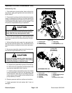
6. Remove generator belt from pulleys and machine.
7. Inspect generator belt and replace belt if worn or
damaged.
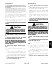
Installation (Fig. 100)
1. Positiongeneratorbelt toengine,generatorand idler
pulleys.
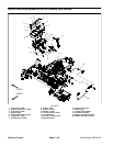
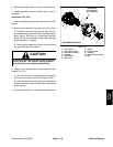
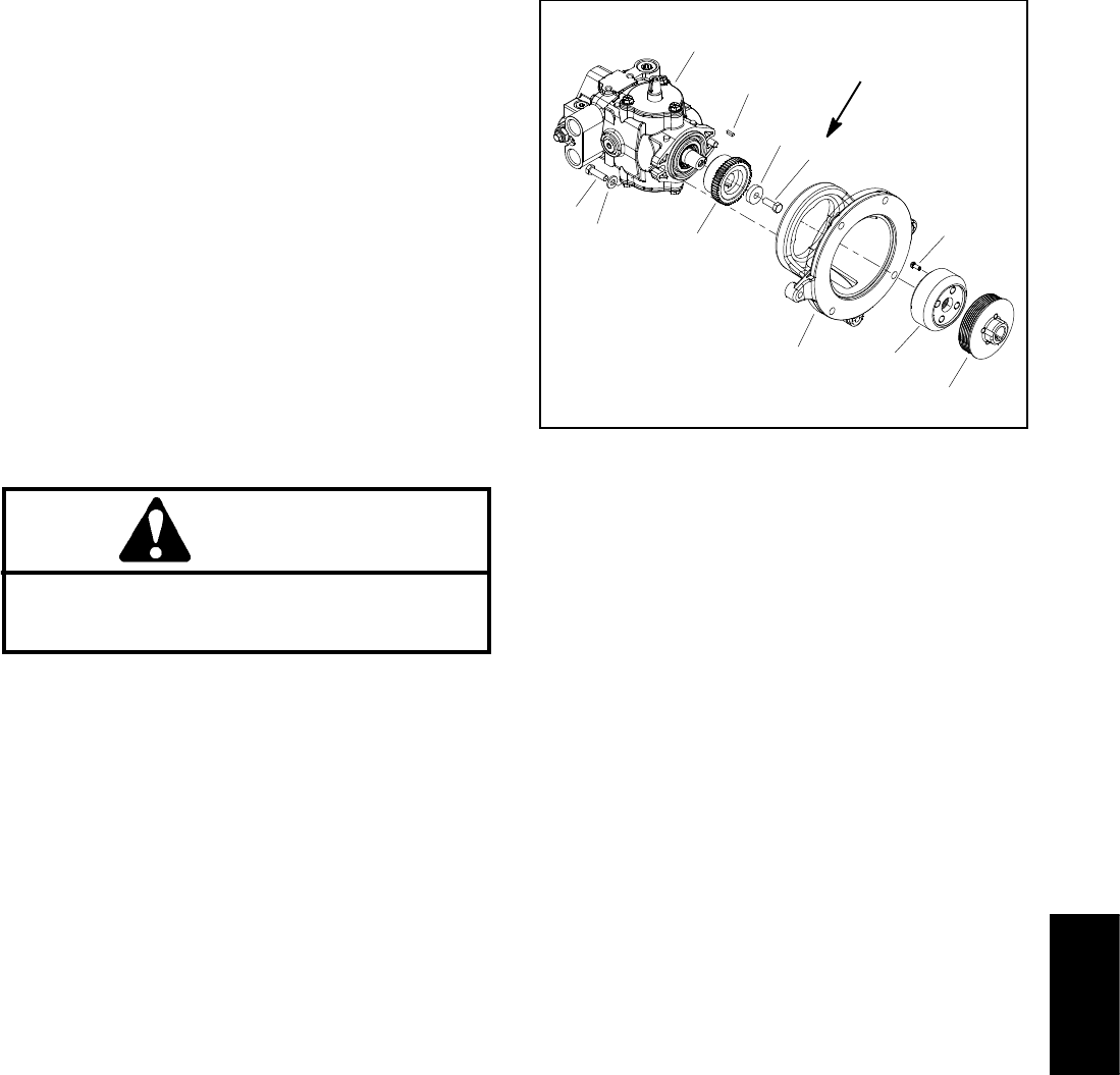
2. Secure pump assembly to pump mount (Fig. 102):
A. Carefully insert coupling on pump shaft into cou-
plingattachedtoengineandslidepumpassemblyto
pump mount. Take care to not damage hydraulic
hoses, traction controlcable or other componentsas
pump assembly is installed.
B. Secure pump assembly to pump mount with two
(2) cap screws and flat washers.
CAUTION
Be careful when applying idler bracket torsion
spring tension. The torsion spring applies a
heavy load that may cause personal injury.
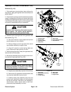
3. Apply torsion spring tension to generator belt idler
bracket (Fig. 101):
A. Use a 3/4” wrench to rotate adjust arm assembly
until hole in arm aligns with hole in engine frame.
B. Insertcap screw through holein spring adjust as-
semblyand engineframe. Installflangenut tosecure
torsion spring.
4. Connect the cutting unit power disconnect couplers.
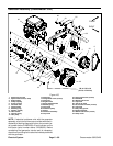
1. Piston pump
2. Cap screw (2 used)
3. Flat washer (2 used)
4. Coupling
5. Pump mount
6. Cap screw
7. Spacer
8. Screw (4 used)
9. Coupling
10. Generator drive pulley
11. Key
Figure 102
GREENSMASTER 3320
27 to 33 ft--lb
(37to44N--m)
7
3
8
1
10
9
2
5
6
4
11
Loctite #242
Electrical
System