


Greensmaster 3320/3420 Hydraulic SystemPage 5 -- 91
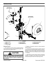
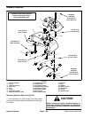
Removal (Fig. 60)
1. Park machine on a level surface, set brake, lower
cutting unitsand stop engine. Removekey from theigni-
tion switch.
CAUTION
Before continuing further, read and become fa-
miliar with General Precautions for Removing
and Installing Hydraulic System Components in
this section.
2. Place a clean container, large enough to collect two
(2) g allons (7.6 liters), under the pump assembly to col-
lect hydraulic oil.
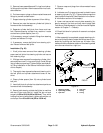
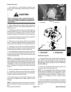
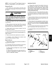
3. Clamp gear pumpinlet hoseto control drainage from
hydraulic reservoir (Fig. 61). Remove pump inlet hose
from gear pump. Release clamp from hose and drain
about two (2) gallons (7.6 liters) of oil from the reservoir.
4. Clamppumpinlet hosetoprevent drainingadditional
hydraulic oil from hydraulic reservoir.
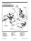
5. Remove four (4) cap screws (item 6), flat washers
(item 7), neoprene washers (item 8) and spacers (item
9) that secure leak detector tank to hydraulic reservoir.
6. Thoroughly clean junction of overflow hose (item 4)
and leak detector tank barb. Loosen hose clamp (item
3) and disconnect overflow hose from tank barb.
7. Lift leak detector tank slightly and clean junction of
valve hose (item 20) at solenoid valve f itting (item 21).
Loosenhoseclamp (item 19) and disconnectvalve hose
at solenoid valve fitting.
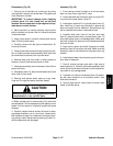
NOTE: On Greensmaster 3320 machines with serial
number above 312000000, the fuel system carbon can-
ister is attached to the leak detector tank (Fig. 62). See
Fuel System Carbon Canister (Serial Number Above
312000000)in theService and Repairssection ofChap-
ter 3 -- Gasoline for information on disconnecting the
canister.
8. Remove leak detector tank assembly from machine.
9. If necessary, remove valve hose (item 20), hydraulic
fitting (item 18) and breather assembly from leak detec-
tor tank. Discard all removed O--rings.
10.Clean leak detector tank and tank components with
clean solvent. Inspect tank for leaks, cracks or other
damage.
NOTE: Ifsolenoid va lve(item16) removalis necessary,
see Leak Detector Solenoid Valve Assembly in this sec-
tion.
Figure 61
1. Gear pump 2. Inlet hose
2
1
Figure 62
1. Carbon cannister
2. Screw (2 used)
3. Cannister bracket
4. Leak detector tank
FRONT
4
1
2
3
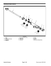
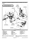
Installation (Fig. 60)
1. If hydraulic fitting (item 18) and breather assembly
were removed from leak detector tank, lubricate and
place new O--rings onto fittings. Install components into
tank openings. Tighten fitting (item 18) from 17 to 21 ft--
lb(23to28N--m).
2. Connect valve hose (item 20) to tank fitting (item 18)
andsecurewithhoseclamp(item19).
NOTE: On Greensmaster 3320 machines with serial
number above 312000000, see Fuel System Carbon
Canister (Serial Number Above 312000000) in the Ser-
vice and Repairs section of Chapter 3 -- Gasoline for in-
formation on connecting the fuel system carbon
canister.
3. Position leak detector tank assembly over hydraulic
reservoir and connect valve hose (item 20) to solenoid
valvefitting(item21).Securehosewithhoseclamp
(item 19).
Hydraulic
System