


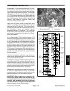

Greensmaster 3320/3420 Page 6 -- 61 Electrical System
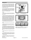
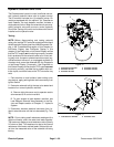
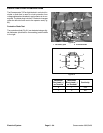
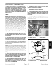
3. Measure coil resistance between terminals 85 and
86 with a multimeter (ohms setting) (Fig. 76). Resist-
ance should be approximately 72 ohms.
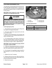
4. Connectmultimeter (ohmssetting) leads torelay ter-
minals 30 and 87. Ground terminal 86 and apply +12
VDC to terminal 85. The relay should make and break
continuity between terminals 30 and 87 as +12 VDC is
applied and removed from terminal 85.
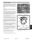
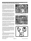
5. Disconnect voltage and leads from the relay termi-
nals. Replace relay if necessary.
6. After testing is completed, secure relay to bracket
and connect wire harness electrical connector to relay.
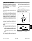
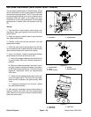
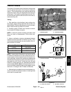
7. Install right side cover n ext to operator seat.
Electrical
System