


Greensmaster 3320/3420 Hydraulic SystemPage 5 -- 57
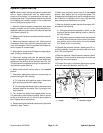
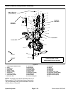
Piston Pump Removal (Fig. 39)
1. Parkmachine on alevel surface,engage theparking
brake, lower the cutting units and stop the engine. Re-
move key from the ignition switch.
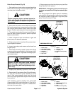
CAUTION
Before continuing further, read and become fa-
miliar with General Precautions for Removing
and Installing Hydraulic System Components in
this section.
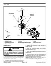
2. Disconnect the traction control cable ball joint (item
20) from the pump lever. Loosen traction control cable
jam nuts that secure traction control cable to the cable
support. Position cable away from the pump assembly.
3. Thoroughlycleanhydraulichose endsandfittings on
gear and piston (traction) pumps to prevent hydraulic
system contamination.
4. Label all hydraulic hose connections on gear and
piston pumps for assembly purposes.
5. Clamp pump suction hose (item 9) to prevent drain-
ing the hydraulic reservoir.
6. Loosen hose clamp and remove suction hose from
the gear pump.
7. Disconnect remaining hydraulic hoses from fittings
ongear andpistonpump assembly.Allowhoses todrain
into a suitable container. Plug hoses and fittings to pre-
vent contamination.
CAUTION
Support the gear and piston pump assembly
when removing its supporting fasteners to pre-
vent it from falling and causing damage or per-
sonal injury.
8. Support pump assembly to prevent it from falling.
9. Remove two (2) cap screws (item 23) and flat wash-
ers ( item 24) that secure pump assembly to pump
mount. Slide pump assembly away from the pump
mount and coupling attached to engine. Remove pump
from machine.
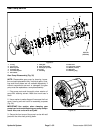
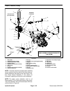
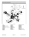
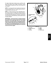
10.If necessary, remove coupling from pump shaft
(Greensmaster 3320 machines shown in Figure 40 or
Greensmaster 3420shown inFigure 41). Locate andre-
trieve key from pump shaft.
11.Remove gear pump from the piston pump (see Gear
Pump Removal in this section).
IMPORTANT: If fittings are to be removed from pis-
tonpump, notepositionof fittingsforassembly pur-
poses.
12.If fitting removal from piston pump is necessary,
mark hydraulic fitting orientation toallow correctassem-
bly. Remove hydraulic fittings and O--rings from piston
pump. Discard removed O--rings.
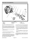
1. Piston pump
2. Cap screw (2 used)
3. Flat washer (2 used)
4. Coupling
5. Pump mount
6. Cap screw
7. Spacer
8. Screw (4 used)
9. Coupling
10. Generator drive pulley
11. Key
Figure 40
GREENSMASTER 3320
27 to 33 ft--lb
(37to44N--m)
7
3
8
1
10
9
2
5
6
4
11
Loctite #242
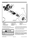
1. Piston pump
2. Cap screw (2 used)
3. Flat washer (2 used)
4. Coupling
5. Cap screw
6. Spacer
7. Engine coupling flange
8. Bell housing
9. Key
10. Generator drive pulley
Figure 41
GREENSMASTER 3420
1
9
6
5
7
8
27 to 33 ft--lb
(37to44N--m)
Loctite #242
3
4
2
10
Hydraulic
System