


Greensmaster 3320/3420 Page 6 -- 29 Electrical System
Verify Diagnostic Display Output Functions
The Hand Held Diagnostic Display has the ability to de-
tect which output solenoids or relays are turned on by
the TEC controller. This is a quick way to determine if a
machine malfunction is electrical or hydraulic.
NOTE: Anopenoutput(e.g.a n unpluggedconnectoror
a broken wire) cannot be detected with the Hand Held
Diagnostic Display.
1. Park machine on a level surface, lower the cutting
units, engage the parking brake and stop the engine.
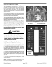
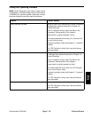
2. Tiltand support operator seat toaccess TEC control-
ler. Locate wire harness connector for Hand Held
Diagnostic Display near TEC controller. Carefully re-
move cap from harness connector (Fig. 29).
3. Connect the Hand Held Diagnostic Display connec-
tor to the wire harness connector. Make sure correct
overlay decal is positioned on the Diagnostic Display
(see Special Tools in this chapter).
4. TurntheignitionswitchtotheRUNposition.
NOTE: The red text on the overlay decal refers to con-
troller inputs and the green text refers to controller out-
puts.
5. The green “OUTPUTS DISPLAYED” LED, on lower
right column of the Hand Held Diagnostic Display,
should be illuminated. If “INPUTS DISPLAYED” LED is
illuminated, p ress the toggle button on the Diagnostic
Displayto change theLED to“OUTPUTS DISPLAYED”.
NOTE: It may be necessary to toggle between “IN-
PUTS DISPLAYED” and “OUTPUTS DISPLAYED” sev-
eral times to perform the following step. To change from
inputs tooutputs, press toggle button once. This may be
done as often as required. Do not press and hold
toggle button.
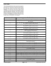
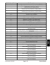
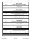
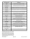
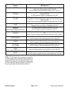
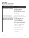
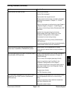
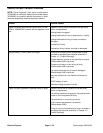
6. Sit on seat, start engine and attempt to operate the
desired function of the machine. The appropriate output
LED’s should illuminate on the Hand Held Diagnostic
Display to indicate t hat the TEC controller is turning on
that function (see Hand Held Diagnostic Display Out-
puts and LED Operation chart on next page). The out-
puts can be checked with the ignition switch in the RUN
position and the engine not running.
NOTE: If the “DIAG. LAMP
” output LED is blinking, this
indicates that the TEC controller has detected a fault
during machine operation. Refer to Diagnostic Light
(Serial Number Below 312000000) or InfoCenter Dis-
play (Serial Number Above 312000000) in this section
for information on retrieval and clearing of controller
faults.
A. Ifthe correctoutput LED’sdo not illuminate, verify
that the required input switches are in the necessary
positionsto allowthatfunction tooccur.Verifycorrect
switch function.
B. If the output LED’s are on as specified, but the
machine does not function properly, consider that
the controller is operating correctly and a problem
exists withsome other component. Inspectelectrical
components and circuit for the affected function.
Also, suspect a non-electrical problem (e.g. hydrau-
lic component problem). Repair as necessary.
C. If each input switch is in the correct position and
functioning correctly, but the output LED’s are not
correctly illuminated, this m ay indicate a controller
problem. If this occurs, contact your Toro Distributor
for assistance.
7. After output function testing is completed, discon-
nect the Hand Held Diagnostic Display from wire har-
ness. Installcapinto wire harness connector.Lower and
secure seat.
1. TEC controller 2. Seat platform
Figure 29
1
2
Electrical
System