


Greensmaster 3320/3420 GroomerPage 9 -- 9
Installation
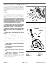
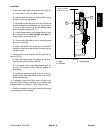
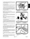
1. If removed, install shaft into groomer cover (Fig. 6):
A. InstallnewO--ringintogrooveofshaft.
B. Apply antiseize lubricant to shaft surface that is
below the retaining ring groove.
C. Slide shaft up through bore of cover and secure
with thrust washer and retaining ring. Position shaft
in cover so that cam point of shaft is located away
from the gasket surface (Fig. 7).
D. Install plunger detent into groomer cover so that
end of plunger if from flush to 0.020” (0.5 mm) ex-
tending from cover surface (Fig. 7).
E. Slide handle into shaft so that it extends toward
the front of the cover.
F. Apply Loctite #242 (or equivalent) to threads of
set screw. Install setscrew intoend ofshaft tosecure
handle in place.
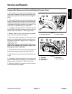
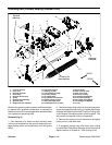
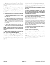
2. Install groomer cover assembly to RH drive plate as-
sembly (Fig. 5):
A. Make sure that handle on groomer cover is ro-
tated toward the front of the machine.
B. Fill groomer cover with approximately five (5)
ounces (142 grams) of Mobil XHP221 grease (or
equivalent).
C. Install new gasket and then groomer cover as-
sembly to RH drive plate. Secure cover with five (5)
flange head screws.
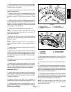
3. If equipped, install rear roller brush to cutting unit
(see Rear Roller Brush Installation in the Service and
Repairs section of Chapter 8 -- DPA Cutting Units).
4. After beltinstallation iscomplete, connectthe cutting
unit power disconnect couplers.
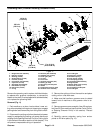
1. Shaft
2. Cam point
3. Plunger detent
Figure 7
2
1
3
Flush to 0.020”
(Flush to 0.5 mm)
Groomer