


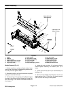

Greensmaster 3320/3420
DPA Cutting Units
Page 8 -- 22
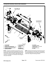
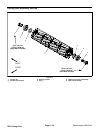
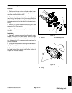
6. Install shoulder bolts (item 4) and flange nuts (item
5) to secure the LH side plates to the crossmember.
Torque the shoulder bolts from 210 to 240 in--lb (24 to
27 N--m).
7. Position crosslink to pitch arms and secure with
washer head screws (item 3).
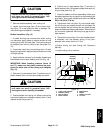
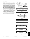
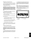
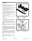
8. If bearing lock nut (RH threads) and reel nut (LH
threads) were loosened during cutting reel service, put
a block of wood between the cutting reel blades to pre-
vent the reel from rotating. Torque bearing lock nut (RH
threads) and reel nut (LH threads) from 90 to 110 ft--lb
(123 to 149 N--m) (Fig. 23).
9. Thoroughly fill spline area of reel nut (left side of cut-
ting reel) with grease.
10.Secure the bedbar assembly to LH side plate (see
Bedbar Installation in this section). Make sure that plas-
tic and steel washers are properly positioned.
11.Secure front and rear rollers to LH side plate (see
Front Roller Installation and Rear Roller Installation in
this section).
12.Adjust cutting unit (see Cutting Unit Operator’s
Manual).
NOTE: The parallel position of the rear roller to the cut-
ting reel is controlled by the precision machined cross-
member and side plates of the cutting unit. If necessary,
the cutting unit side plates can be loosened and a slight
adjustment can be made to parallel the rear roller with
the cutting reel (see Leveling Rear Roller in the Set--Up
and Adjustments section of this Chapter).
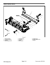
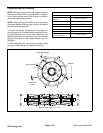
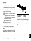
13.Install new O--ring (item 12) on weight. Secure
weight assembly (items 10and 20) toRH side plate with
two (2) cap screws and nuts.
14.If cutting unit is equipped with optional groomer or
rear roller brush, install componentsfor those options to
cutting unit. SeeService andRepairs section ofChapter
8 -- Groomer for information on groomer. See Rear Roll-
er Brush in this section for information on rear roller
brush.
15.Install cutting unit to the machine.