


Greensmaster 3320/3420Page 6 -- 60Electrical System
Main Power, Electric Cutting Reels Enable, Charge Circuit (Greensmaster 3320), Glow
(Greensmaster 3420) and Fan (Greensmaster 3420) Relays
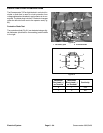
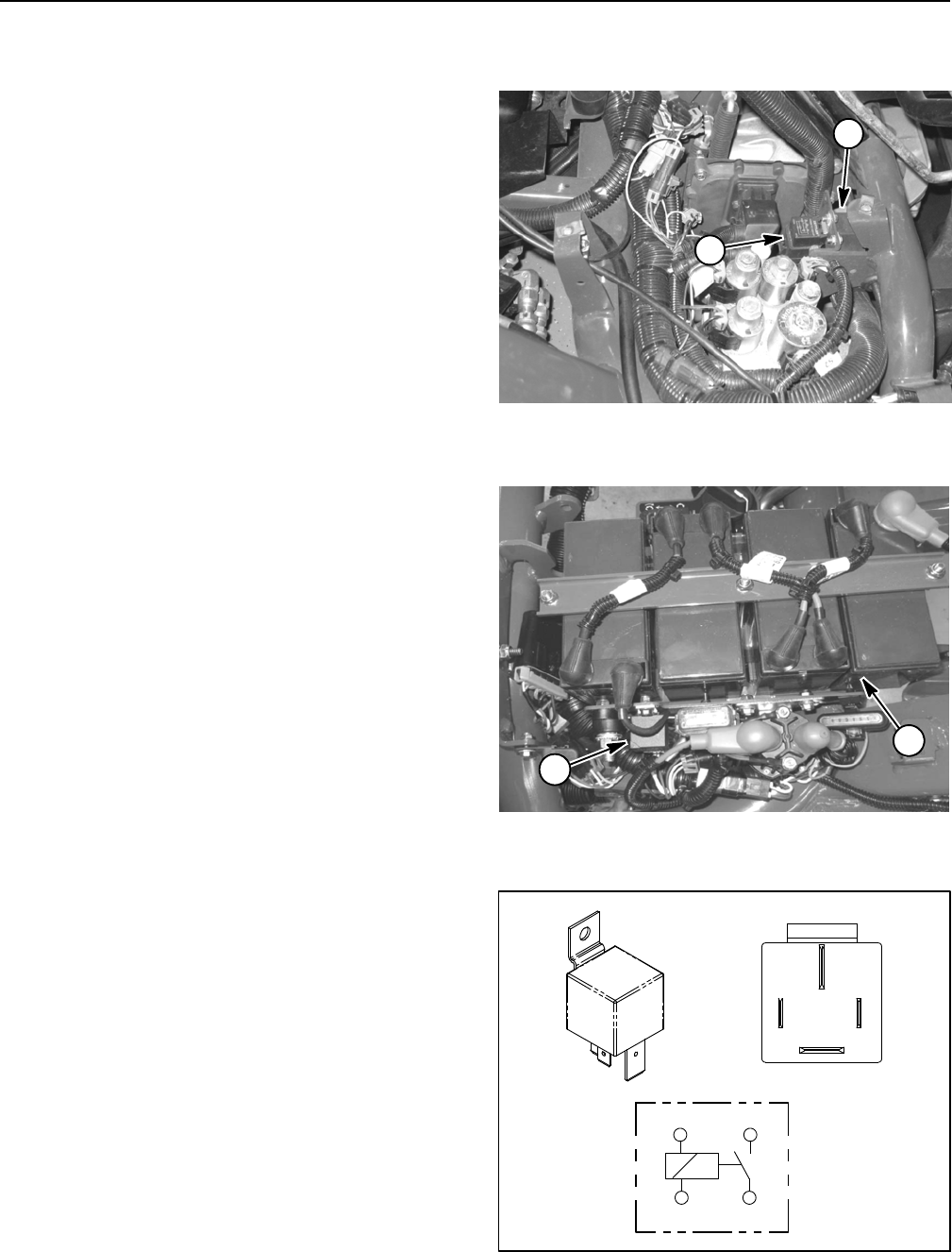
The Greensmaster TriFlex Hybrid electrical system in-
cludes several identical, four (4) terminal relays for cur-
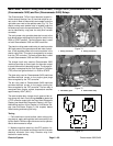
rent control. Most of these relays are located under the
right side cover next to the operator seat (Fig. 74). The
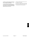
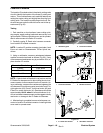
electric cutting reels enable relay is located under the
left side covernext to theoperator seat (Fig.75). Relays
canbeidentifiedbyatagneartherelaywireharness
connector.
The main power relay provides electrical current to the
fuse blocks when energized by the ignition switch in the
RUN or START position. The main power relay is used
on both Greensmaster 3320 and 3420 machines.
The electric cutting reels enable relay is used to provide
48V logic power tothe generator andreel motor control-
lers. It also supplies power to the main contactor in the
electric reel circuit. This relay is energized by an output
from the TEC controller. The reels enable relay is used
on both Greensmaster 3320 and 3420 machines.
The charge circuit relay used on Greensmaster 3320
machines provides a current path for alternator output
toreachthemachine’selectricalsystem.Thechargecir-
cuit relay is energized by the Toro Electronic Controller
(TEC) when the ignition switch is in RUN or START.
The glow relay used on Greensmaster 3420 machines
provides electrical current to the engine glow plugs
when energized by the TEC controller.
The fan relay used on Greensmaster 3420 machines
provides electrical current to the engine cooling fan
when energized by the TEC controller. The fan relay is
energized when engine coolant temperature reaches
approximately 185
o
F(85
o
C).
The reels enable relay, charge circuit, glow and fan re-
lays along with their circuit wiring should be tested as
a TEC controller output with the Hand Held Diagnostic
Display (see Hand Held Diagnostic Display in the Trou-
bleshooting section of this chapter) or InfoCenter Dis-
play (see InfoCenter Display in this chapter) before
disconnecting and testing the relay.
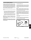
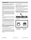
Testing
1. Park machine on a level surface, lower cutting units,
stop engine, apply parking brake and remove key from
ignitionswitch. Remove rightside covernext tooperator
seat to allow access to relays.
2. Make sure ignition switch is in the OFF position. Lo-
cate the relay to be tested and disconnect wire harness
electrical connector from relay. Remove relay from
bracket for easier testing.
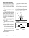
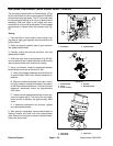
1. Relay (4 terminal) 2. Relay (5 terminal)
Figure 74
2
1
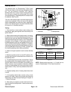
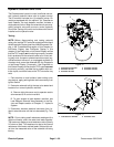
1. 48V battery pack 2. Reels enable relay
Figure 75
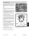
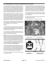
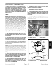
1
2
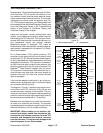
Figure 76
86 87
85 30
85 86
87
30