


Greensmaster 3320/3420Groomer Page 9 -- 18
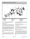
Grooming Reel Bearing Replacement
Bearing Removal
1. Park machine on a clean, level surface. Lower cut-
tingunits completely to theground,stop engine,engage
parking brake and remove key from the ignition switch.
2. Disconnectthecutting units from the electricalpower
supply by separating the cutting unit power disconnect
couplers (see Opening Electrical Circuitto Cutting Units
in the General Information section of this chapter). This
will prevent unexpected cutting unit operation.
3. Remove the cutting unit from the machine and place
cutting unit on a flat work area.
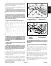
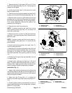
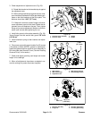
4. To remove groomer drive plate assembly from right
side of cutting unit, remove front roller, grooming reel
andthendrive plate assembly(see GroomingReel(For-
ward Rotating or Counter Rotating) in this section).
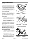
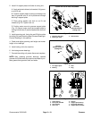
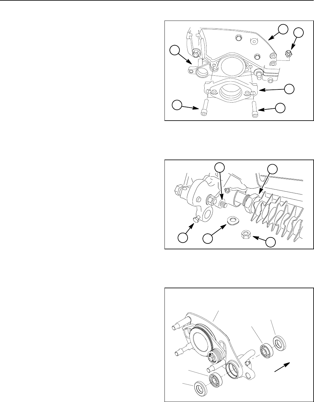
5. To remove support plate assembly from left side of
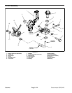
cutting unit (Fig. 19):
A. Remove two (2) socket head screws and lock
nuts that secure motor mount tocutting unit(Fig. 19).
Remove motor mount from cutting unit.
B. Remove lock nut and spring washer that secure
LH groomer arm liftrod tosupport plate(Fig. 20).Re-
move support plate from cutting u nit.
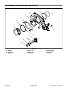
6. Remove grooming reel seals and bearings from RH
drive plate and LH support plate assemblies (Figs. 21,
22 and 23). Discard all removed seals and bearings.
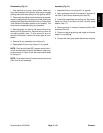
Bearing Installation
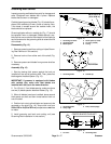
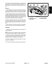
1. Installnew grooming reelbearings and sealsinto RH
drive plate and LH support plate assemblies ( Fig. 24):
IMPORTANT: Bearings should be installed with ex-
tended inner races toward center of housing. Also,
apply pressure equally to inner and outer bearing
races when installing bearings.
A. Press new outer bearing fully to shoulder of RH
drive plate bore. Then, install new inner bearing until
inner race contacts outer bearing race.
B. Press new bearing into LH support plate u ntil it is
flush with shoulder of bearing bore.
C. Installnewsealsinto groomer sideplates.NOTE:
Seals should be installed so the lip side of the seal
will facethe center ofthe cutting reel. Whenbearings
are greased, grease will purge from inner seals.
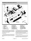
1. Socket head screw
2. Motor mount
3. Groomer side plate (RH)
4. Cutting unit
5. Lock nut (2 used)
Figure 19
4
2
1
3
1
5
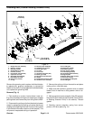
1. Front roller cap screw
2. Grooming reel assembly
3. Lock nut
4. Spring washer
5. Groomer arm lift rod
Figure 20
4
2
1
3
5
1. RH drive plate assy
2. Bearing (2 used)
3. Seal (2 used)
Figure 21
Seal lips
(toward center of
cutting unit)
3
2
2
3
1
FORWARD ROTATING GROOMER