


Groundsmaster 4500--D/4700--D Hydraulic SystemPage 4 -- 57
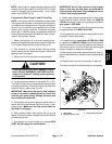
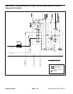
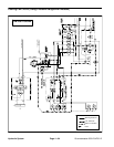
NOTE: GearpumpP1 supplieshydraulic flowtocutting
decks 5, 3 and 2 (also deck 7 onthe GM 4700--D). Gear
pump P2 supplies flow to cutting decks 1 and 4 (also
deck 6 on the GM 4700--D).
Procedure for Gear Pump P1 and P2 Flow Test
NOTE: Overa periodof time,thegears andwear plates
in the gear pump can wear.A worn pump will by pass oil
andmake thepump lessefficient.Eventually,enoughoil
loss will occur to cause the cutting deck motors to stall
under heavy cutting conditions. Continued operation
with a worn, inefficient pump can generate excessive
heat and cause damage to the seals and other compo-
nents in the hydraulic system.
1. Make sure hydraulic oil is at normal operating tem-
peraturebyoperatingthemachineforapproximatelyten
(10) minutes. Make sure the hydraulic tank is full.
2. Park machine on a level surface with the cutting
decks lowered and off. Make sure engine is off and the
parking brake is engaged.
3. Raise hood to allow access to pump assembly.
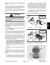
CAUTION
Prevent personal injury and/or damage to equip-
ment. Read all WARNINGS, CAUTIONS and Pre-
cautions for Hydraulic Testing at the beginning
of this section.
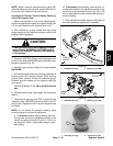
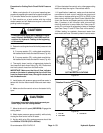
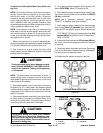
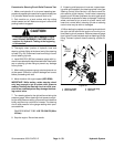
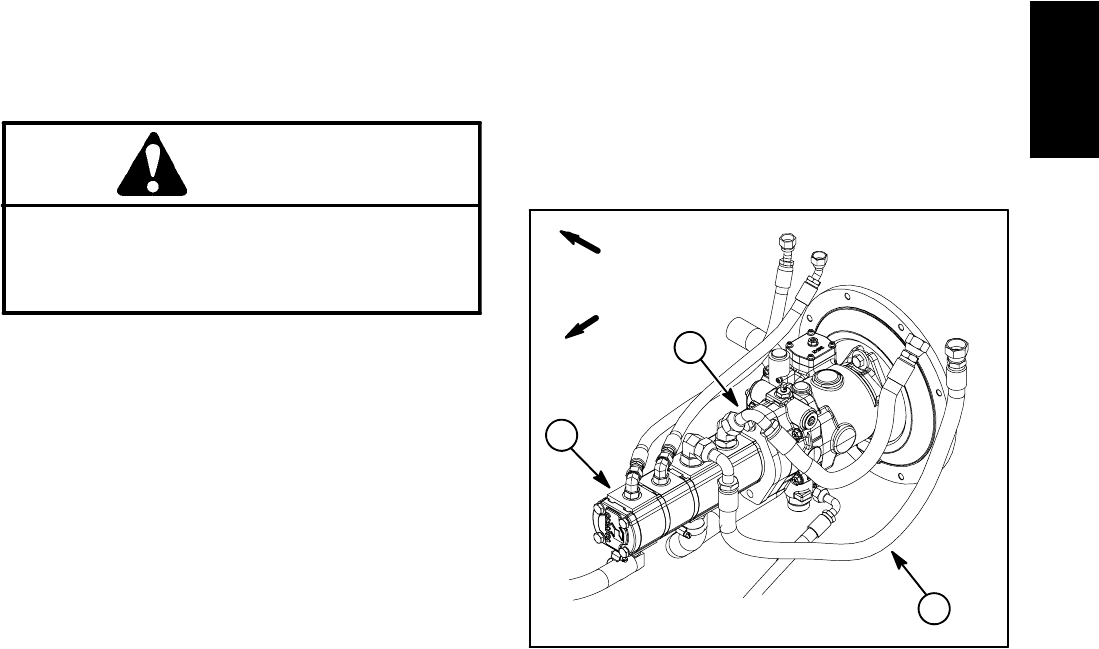
4. Locate gear pump section to be tested (P1 or P2).
Thoroughlyc lean junctionof appropriatehydraulic hose
and gear pump fitting. Disconnect hydraulic hose from
hydraulic fitting in gear pump (Fig. 48).
IMPORTANT: Make sure that the oil flow indicator
arrow on the tester is showing that the oil will flow
from the gear pump fitting, through the tester and
into the disconnected hose.
5. Install tester with pressure gauge and flow meter in
series with the disconnected hose and fitting in gear
pump section. Make sure the flow control valve on
the tester is fully open.
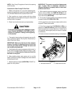
6. After installing tester, start engine and run at idle
speed. Check for hydraulic leakage and correct before
proceeding with test.
7. Start engine and move throttle to full speed (2870
RPM). Do not engage the cutting decks.
IMPORTANT: Do not fully restrict oil flow through
tester. In this test, the flow tester is positioned be-
fore thecircuit reliefvalve. Pumpdamage can occur
if the oil flow is fully restricted.
8. Watch tester pressure gauge carefully while slowly
closing the flow control valve on tester until 2000 PSI
(138 bar) is obtained. Verify witha phototac that the en-
gine speed is 2870 RPM.
9. For a pump in good condition, flow indication should
be approximately 11.5 GPM (43.5 LPM).
10.Fully open flow control valve on tester and then shut
engine off. Record test results.
11.If measured flow is less than 9.6 GPM (36.3 LPM)
or apressure of2000 PSI(138 bar) cannotbe obtained,
check for restrictionin the pumpintake line(including oil
filter and oil cooler). If line is not restricted, remove gear
pump and repair or replace as necessary.
12.After testing is complete, disconnect tester from hy-
draulic hose and fitting. Connect hose to the gear pump
fitting.
13.Repeat test for second pump section if required.
14.Lower and secure hood after testing is completed.
1. Gear pump
2. Pump section P1 hose
3. Pump section P2 hose
Figure 48
FRONT
RIGHT
1
3
2
Hydraulic
System