


Groundsmaster 4500--D/4700--DPage 3 -- 14Kubota Diesel Engine
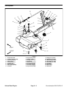
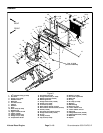
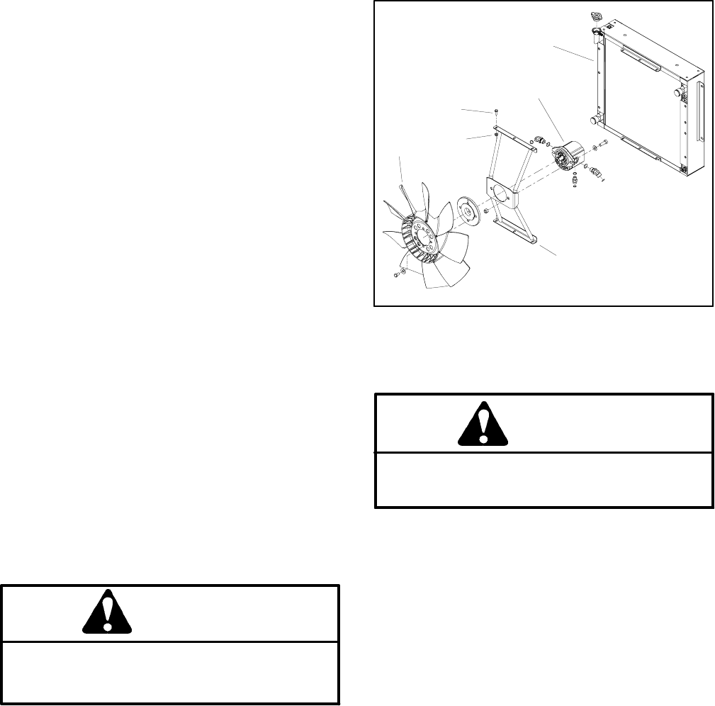
11.Remove fan motor and fan assembly (Fig. 13).
A. To prevent contamination of hydraulic system,
thoroughly clean exterior of fan motor and fittings.
B. Disconnect hydraulichoses from cooling fan mo-
tor. Putcaps orplugs onfittings andhoses toprevent
contamination. Label hydraulic lines for proper as-
sembly.
C. Remove six ( 6) cap screws and flange nuts that
secure fan motor bracket to radiator.
D. Carefullyremove fanmotor, fan andmotor brack-
et assembly from machine.
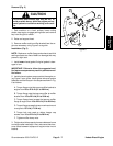
IMPORTANT: The hydraulic pump assembly canre-
main in machine during engine removal. To prevent
pump from shifting or falling, make sure to support
pump assembly before pump mounting fasteners
are removed.
12.Support hydraulic pump assembly. Remove fasten-
ers that secure pump assembly to engine (see Pump
Assembly Removal in the Service and Repairs section
of Chapter 4 -- Hydraulic System).
13.Make sure all cableties securing the wiringharness,
fuel lines or hydraulic hoses to the engine are removed.
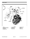
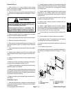
14.Connect lift or hoist to the lift tabs on engine.
15.Remove flange nuts, rebound washers and cap
screws that secure the engine mounts to the rubber en-
gine supports.
CAUTION
One person should operate lift or hoist while a
second person guides the engine out of the ma-
chine.
IMPORTANT: Make sure to not damage the engine,
fuel lines, hydraulic lines, electrical harness or oth-
er parts while removing the engine.
16.Carefully lift engine from the machine.
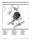
17.If necessary, removeenginemounts fromtheengine
using Figure 10 as a guide.
Engine Installation (Fig. 10)
1. Ifremoved,install enginemounts to theengineusing
Figure 10 as a guide.
2. Connect lift or hoist to the lift tabs on engine.
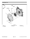
Figure 13
1
2
3
4
5
6
1. Fan
2. Fan motor bracket
3. Fan motor
4. Cap screw (6 used)
5. Flange nut (6 used)
6. Radiator
CAUTION
One person should operate lift or hoist while a
second person guides the engine into the ma-
chine.
IMPORTANT: Make sure to not damage the engine,
fuel lines, hydraulic lines, electrical harness or oth-
er parts while installing the engine.
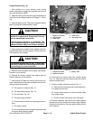
3. Carefully lower engine into the machine.
4. Align engine to the engine supports and hydraulic
pumpinputshaft.Secureenginetoenginesupports with
cap screws, rebound washers and flange nuts.
5. Secure hydraulic pump assembly to engine (see
Pump Assembly Installation in the Service and Repairs
section of Chapter 4 -- Hydraulic System).
6. Install fan motor and fan assembly (Fig. 13).
A. Carefullypositionfanmotor, fanand motorbrack-
et assembly to radiator.
B. Secure fan motor bracket to radiator with six (6)
cap screws and flange nuts.
C. Remove caps and plugs placed in hoses and fit-
tings during removal to prevent contamination.
D. Connect hydraulic hoses to cooling fan motor
(see Hydraulic Hose and Tube Installation in the
GeneralInformationsection ofChapter4 -- Hydraulic
System).