


Groundsmaster 4500--D/4700--D Hydraulic SystemPage 4 -- 83
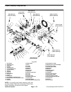
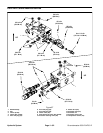
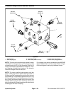
NOTE: The ports on the manifold are marked for easy
identification of components (e.g. P1 is a piston pump
connection port and SV is the location for the solenoid
valve). See Hydraulic Schematics in Chapter 9 -- Fold-
out Drawings to identify the function of the hydraulic
lines and cartridge valves at each port.
NOTE: The 4WD/2WD control manifold uses several
zero leak plugs. These plugs have a tapered sealing
surface onthe plug headthat is designedto resist vibra-
tion induced plug loosening. The zero leak plugs also
havean O--ring asa secondaryseal. If zeroleak plugre-
moval is necessary,lightly rap the plug head using a pin
punch and hammer before using an allen w rench to re-
move the plug: the impact will allow plug removal with
less chance of damage to the head of the plug.
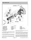
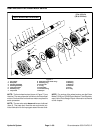
IMPORTANT: A flow control orifice (item 3) is lo-
cated beneath the plug in 4WD/2WD control man-
ifold ports OR1 and OR2. If either of these plugs is
removed from the manifold, make sure to remove
orificeand labelitsposition forassembly purposes.
When installing the orifice in the manifold, make
sure that the orifice is flat in the base of the port.
Manifold damage is possible if the orifice is cocked
in the port.
IMPORTANT: An orifice disc (item 4) is located be-
neaththe4WD/2WDcontrolmanifoldsolenoidvalve
(SV). If this valve is removed from the manifold,
make sure to remove orifice and label its position
for assembly purposes. When installing the orifice
in the manifold, make sure that the orifice is flat in
the base of the port.
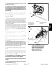
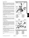
Cartridge Valve Service
1. Make surethe manifold isclean before removingthe
cartridge valve.
2. If cartridge is solenoid operated, remove nut secur-
ing solenoid to the cartridge valve. Carefully slide sole-
noid off the valve.
IMPORTANT: Use care when handling the cartridge
valve. Slight bending or distortion of the stem tube
can cause binding and malfunction.
3. Remove cartridge valve with a deep socket wrench.
Note correct location for O--rings, sealing rings and
backup rings. Remove and discard seal kit.
4. Visually inspect the port in the manifold for damage
to the sealing surfaces, damaged threads and contami-
nation.
5. Visually inspect cartridge valve for damaged sealing
surfaces and contamination.
A. Contaminationmay cause valvesto stick orhang
up.Contaminationcanbecomelodgedinsmallvalve
orifices or seal areas causing malfunction.
B. If valve sealing surfaces appear pitted or dam-
aged, the hydraulic system may be overheating or
there may be water in the system.
CAUTION
Use eye protection such as goggles when using
compressed air.
6. Clean cartridge valve using clean mineral spirits.
Submerge valvein clean mineralspirits toflush out con-
tamination.Particlesas fine astalcumpowdercanaffect
the operation of high pressure hydraulic valves. If car-
tridgedesignallows,use awood orplastic probetopush
the internal spool in and out 20 to 30 times to flush out
contamination. Beextremely careful not todamage car-
tridge. Use compressed air for cleaning.
7. Install the cartridge valve:
A. Lubricatenew seal kitcomponents with clean hy-
draulic oil and install on valve. The O--rings, sealing
ringsandbackup rings mustbearranged properlyon
the cartridge valve for proper operation and sealing.
IMPORTANT: Use care when handling the valve
cartridge. Slight bending or distortion of the
stem tube can cause binding and malfunction.
B. Thread cartridge valve carefully into manifold
port. The valve should go in easily without binding.
C. Torquecartridgevalve usingadeep sockettoval-
ue identified in manifold illustration.
D. If cartridge is solenoid operated, carefully install
solenoid coil to the cartridge valve. Torque nut to 5
ft--lb (6.8 N--m).
8. If problems still exist, remove valve and clean again
or replace valve.
Hydraulic
System