


Groundsmaster 4500--D/4700--D Page 5 -- 31 Electrical System
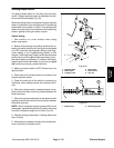
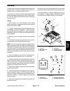
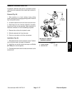
Temperature Sender
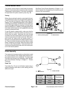
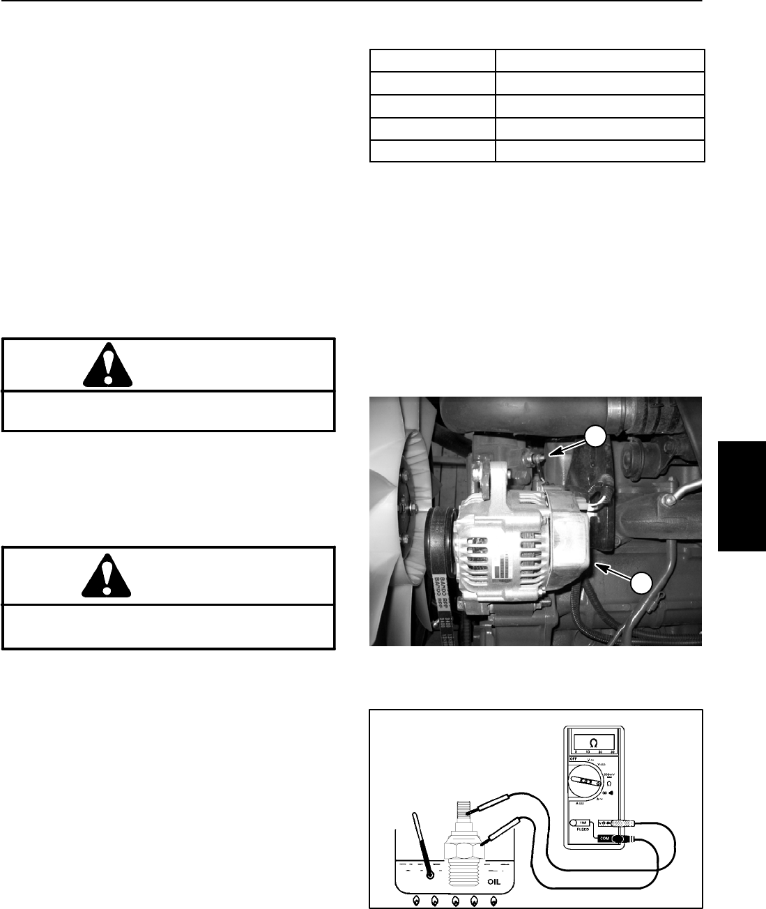
The temperature sender is located near the alternator
onthe waterflange attachedto theengine cylinderhead
(Fig. 44). There is a gray wire attached to the terminal
of the sender.
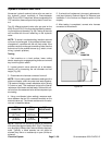
The resistance of the temperature sender reduces as
the engine coolant temperature increases. The chang-
ing resistance of the temperature sender signals the
console temperature gauge to indicate engine coolant
temperature during machine operation.
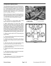
Temperature Sender Test
1. Park machine on a level surface, lower cutting
decks, stop engine, apply parking brake and remove
key from ignition switch. Open hood to gain access to
engine.
CAUTION
Make sure engine is cool before removing the
temperature sender from engine.
2. Lower coolant level in the engine and remove the
temperature sender from water flange.
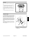
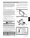
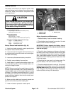
3. Put sender in a container of oil with a thermometer
and slowly heat the oil (Fig. 45).
CAUTION
Handle the hot oil with extreme care to prevent
personal injury or fire.
NOTE: Prior to taking resistance readings with a digital
multi meter, shortthe metertest leadstogether. Theme-
ter will display a small resistance value (usually 0.5
ohms or less). This resistance is due to the internal re-
sistance of the meter and test leads. Subtract this value
fromfrom themeasured valueof thecomponent youare
testing.
4. Check resistance of the sender with a multimeter
(ohms setting) as the temperature increases. Replace
sender if specifications are not met.
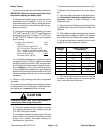
OIL TEMP
TEMP SENDER RESISTANCE
100
o
F(38
o
C) 460 ohms (approximate)
160
o
F(71
o
C) 140 ohms (approximate)
200
o
F(93
o
C) 54 to 78 ohms
221
o
F (105
o
C) 50 ohms (approximate)
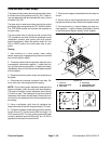
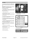
5. Install sender to the water flange.
A. Clean threads of water flange and sender thor-
oughly. Apply thread sealant to the threads of the
sender.
B. Screwsender intothe waterflange. Torquesend-
er from 16 to 20 ft--lb (21.7 to 27.1 N--m).
C. Connect gray wire to sender. Apply skin--over
grease (Toro Part No. 505--47) to sender terminal.
6. Fill engine cooling system.
Figure 44
1. Temperature sender 2. Alternator
2
1
Figure 45
Electrical
System