


Groundsmaster 4500--D/4700--DPage 5 -- 2Electrical System
General Information
Operator’s Manual
The Operator’s Manual provides information regarding
the operation, general maintenance and maintenance
intervals for your Groundsmaster machine. Refer to the
Operator’s Manual for additional information when ser-
vicing the machine.
Toro Electronic Controllers (TEC)
Groundsmaster 4500--D machines use a single Toro
Electronic Controller (TEC--5002) to manage machine
electrical functions. Groundsmaster 4700--D machines
use two (2) Toro Electronic Controllers (TEC--5002 and
TEC--5001).
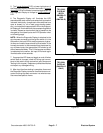
The controllers are microprocessor controlled that
sense the condition of various machine switches (in-
puts) and direct electrical power to control appropriate
machinefunctions (outputs)based onthes tate ofthein-
puts. The status of inputs to the controllers as well as
outputs from the controllers can be checked with the
Diagnostic Display (see Special Tools).
The controllers on the Groundsmaster 4700--D appear
identical butthey aredifferentin termsof theconnectors
and internal hardware. They are arranged in a master
(TEC--5002) / slave (TEC--5001) configuration and
therefore cannot be interchanged. Communication be-
tween the two controllers on the Groundsmaster
4700--D is provided with a CAN--bus system (see be-
low).
Because of the solid state circuitry built into the Toro
Electronic Controller (TEC), there is no method to test
it directly. The TEC may be damaged if an attempt is
made to test it with an electrical test device, such as a
digital multimeter.
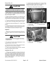
IMPORTANT: Before performingany weldingon the
machine, disconnect the battery cables from the
battery, disconnect the wire harness connectors
from the Toro Electronic Controller(s) and discon-
nect the terminal connector from the alternator to
prevent damage to the machine electrical system.
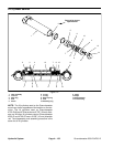
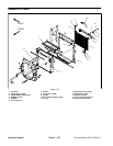
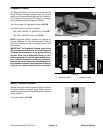
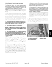
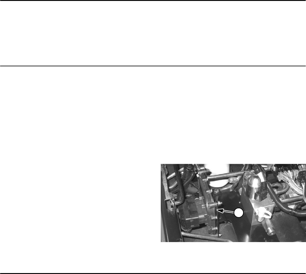
Figure 1
1
1. Toro Electronic Controller (GM 4500--D shown)
CAN--bus Communications (Groundsmaster 4700--D)
The two (2) TEC controllers (TEC--5002 and
TEC--5001) used on the Groundsmaster 4700--D com-
municate with each other on a CAN--bus system. Using
this system allows the traction unit to fully integrate all
the different electrical components of the tractor and
bring them together as one. The CAN--bus system re-
ducesthenumberofelectricalcomponentsandconnec-
tions used on the machine and allows the number of
wires in the wire harness to be significantly reduced.
CAN identifies the Controller Area Network that is used
betweenthe controllerson theGroundsmaster 4700--D.
Two (2)specially designed,twisted cablesform thebus.
These cables provide the data pathways between the
controllers(TEC--5002 andTEC--5001)usedon thema-
chine. The engineering term for these two cables are
CAN High and CAN Low. At the ends of the twisted pair
of bus cables are 120 ohm termination resistors.
Each of the components that is controlled by the CAN--
bus link only needs four (4) cables to operate and com-
municate to the system: CAN High, CAN Low, B+
(power) and ground.