


Groundsmaster 4500--D/4700--D Page 5 -- 19 Electrical System
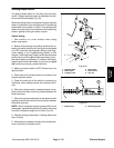
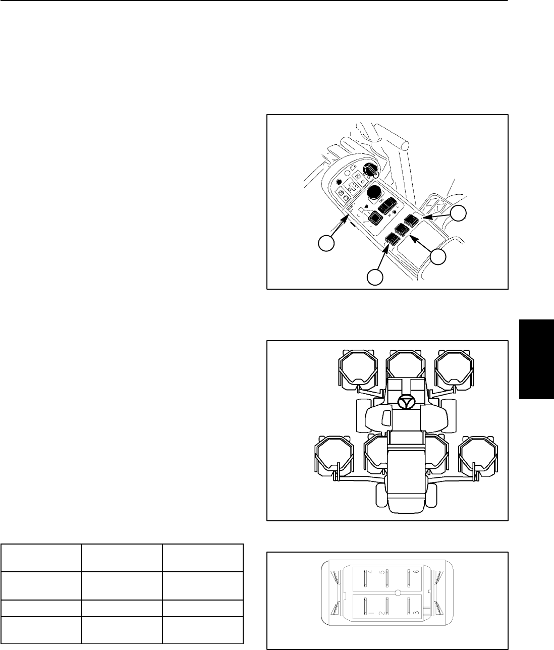
Cutting Deck Lift Switches
The cutting deck lift switches are used as inputs for the
TEC controllerto raise or lowerthe cutting decks.When
the front of a lift switch is depressed and held, the con-
trolled decks will lower. When the rear of a lift switch is
depressed and held,the controlled decks willraise. The
decks will remain in position when the switch is re-
leased. The lift switches are located on the console arm
(Fig. 20).
NOTE: To lower the cutting decks, traction speed has
to be in low range (4WD). Also, to raise or lower the
decks, the seat has to be occupied.
Testing
1. Before disconnecting the lift switch for testing, the
switch and its circuit wiring should be tested as a TEC
input with the Diagnostic Display (see Diagnostic Dis-
playintheTroubleshootingsectionofthischapter).Ifthe
Diagnostic Display verifies that the lift switch and circuit
wiring arefunctioning correctly,no furtherswitch testing
is necessary. If, however, the Display determines that
the lift switch and circuit wiring are not functioning cor-
rectly, proceed with test.
2. Make sure ignition switch is OFF. Remove key from
ignition switch.
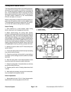
3. Disassemble console arm to gain access to cutting
deck lift switches (see Console Arm Disassembly in the
Service and Repairs section of C hapter 7 -- Chassis).
4. Disconnect harness electrical connector from the lift
switch.
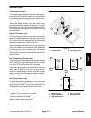
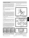
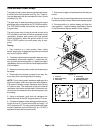
5. The switch terminals are marked as shown in Figure
22. The circuit logic of the lift switches is shown in the
chartbelow. Withtheuse ofamultimeter (ohmssetting),
theswitchfunctionsmaybetestedto determinewhether
continuity exists between thevarious terminals for each
position.Verify continuitybetween switchterminals.Re-
place switch if testing identifies a faulty switch.
SWITCH
POSITION
CLOSED
CIRCUITS
OPEN
CIRCUITS
DECK LOWER 2+3
5+6
2+1
5+4
NEUTRAL NONE ALL
DECK RAISE 2+1
5+4
2+3
5+6
6. Iflift switchtests correctlyand circuitproblem stillex-
ists, checkwire harness (see Electrical Schematics and
Wire Harness Drawings in Chapter 9 -- Foldout Draw-
ings).
7. After testing is completed, connect wire harness
connector to the lift switch.
8. Assemble consolearm (see Console Arm Assembly
in the Service and Repairssection of Chapter 7 -- Chas-
sis).
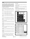
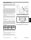
1. Console arm
2. Lift switch (#1 to #5)
3. Lift switch (GM4700 #7)
4. Lift switch (GM4700 #6)
Figure 20
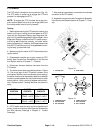
1
2
3
4
Figure 21
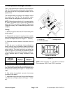
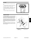
#4 #1 #5
#7
(GM4700)
#6
(GM4700)
#3#2
CUTTING
DECK
LOCATIONS
Figure 22
BACK OF SWITCH
NOTE: Lift switch terminals 4, 5 and 6 are not used on
Groundsmaster 4500--D and 4700 --D machines.
Electrical
System