


Groundsmaster 4500--D/4700--D Hydraulic SystemPage 4 -- 123
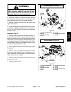
WARNING
If lift manifold is attached to machine, make sure
that cutting decks are fully lowered before loos-
ening hydraulic lines, cartridge valves or plugs
from lift manifold. If decks are raised as compo-
nents are loosened, decks may drop unexpect-
edly.
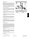
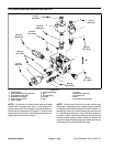
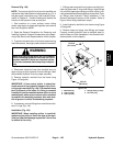
For solenoid and control valve service procedures, see
4WD/2WD Control Manifold Service in this section. Re-
fer to Figures 101 and 102 for c artridge valve and plug
installation torque.
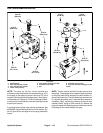
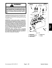
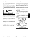
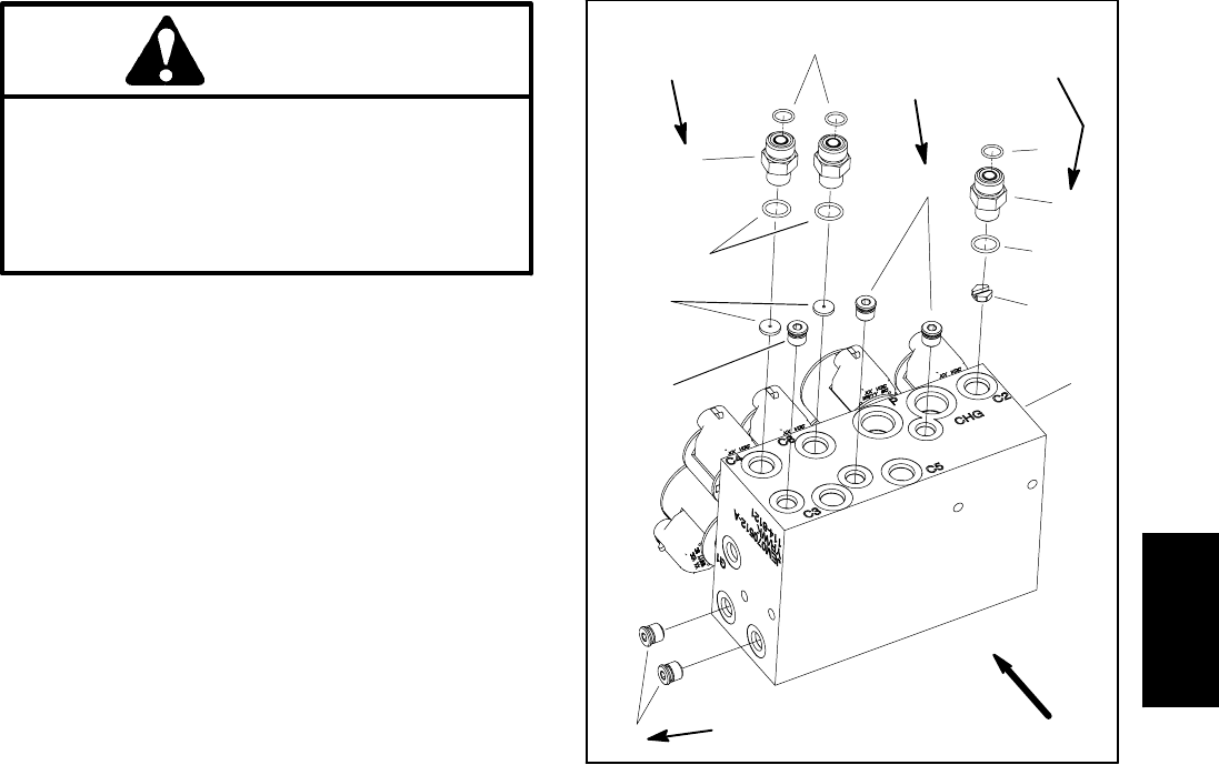
IMPORTANT: A flow control orifice is placed be-
neath severalof thehydraulic fittingson thelift con-
trolmanifold(Fig.102). Theliftmanifolduses two(2)
different orificesizes. Ifa fitting isremoved fromthe
lift control manifold and an orifice is in the manifold
port, make sure to remove orifice and label its posi-
tion for assembly purposes. Also note location of
groove in orifice for assembly purposes.
IMPORTANT: When installing orifice in manifold
(Fig. 102), make sure that orifice is flat in the baseof
the manifold port. Manifold damage is possible if
the orifice is cocked in the cavity.
1. Manifold body
2. Straight fitting (3 used)
3. Zero leak plug (#4)
4. Orifice (0.063)
5. Orifice (0.080)
6. O--ring
7. O--ring
Figure 102
4
6
3
2
1
5
2
3
3
UP
6
7
7
25 ft--lb
(33.9 N--m)
20 ft--lb
(27.1 N--m)
25 ft--lb
(33.9 N--m)
20 ft--lb
(27.1 N--m)
Hydraulic
System