


Groundsmaster 4500--D/4700--DHydraulic System Page 4 -- 122
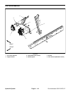
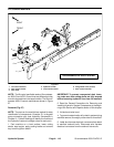
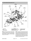
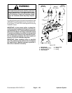
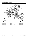
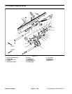
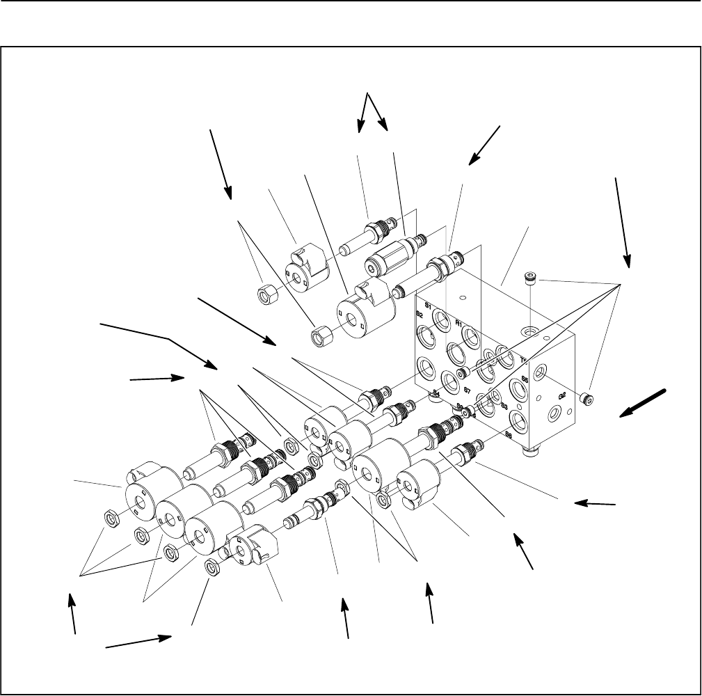
Lift Control Manifold Service (GM 4700--D)
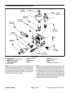
1. Manifold body
2. Nut
3. Zero leak plug (#4)
4. Relief valve (port R1)
5. Proportional relief valve (port TS)
6. Solenoid valve (ports S2, S3, S7, S8)
7. Solenoid valve (port S1)
8. Solenoid valve (ports S4, S6, S9)
9. Solenoid valve (port S5)
10. Solenoid coil (5 used)
11. Solenoid coil (5 used)
12. Nut
Figure 101
7
4
6
10
3
11
12
2
1
5
9
8
6
8
10
10
10
11
11
11
5 ft--lb
(6.8 N--m)
20 ft--lb
(27.1 N--m)
25 ft--lb
(33.9 N--m)
20 ft--lb
(27.1 N--m)
25 ft--lb
(33.9 N--m)
25 ft--lb
(33.9 N--m)
20 ft--lb
(27.1 N--m)
20 ft--lb
(27.1 N--m)
5 ft--lb
(6.8 N--m)
12
5 ft--lb
(6.8 N--m)
12
12
5 ft--lb
(6.8 N--m)
UP
20 ft--lb
(27.1 N--m)
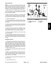
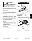
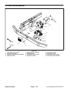
NOTE: The ports on the manifold are marked for easy
identification of components (e.g. P is the gear pump
connection port and R1 is the relief valve port). See Hy-
draulic Schematics in Chapter 9 -- Foldout Drawings to
identify the function of the hydraulic lines and cartridge
valves at each port location.
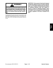
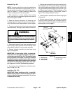
NOTE: The lift control manifold uses several zero leak
plugs. These plugs have a tapered sealing surface on
theplug headthat isdesigned toresistvibration induced
plugloosening. Thezero leak plugsalsohave anO--ring
as a secondary seal. If zero leak plug removal is neces-
sary, lightly rap the plug head using a punch and ham-
mer before using an allen wrench to remove the plug:
the impact will allow plug removal with less chance of
damage to the socket head of the plug.