


Groundsmaster 4500--D/4700--D Hydraulic SystemPage 4 -- 29
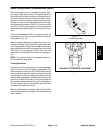
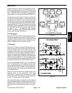
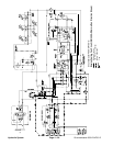
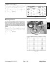
Steering Circuit
A four section gear pump is coupled to the piston (trac-
tion) pump. Thegear pump section P3 supplieshydrau-
lic flow to the steering control valve and the lift/lower
controlvalve.Pumphydraulicflowis deliveredtothetwo
circuits througha proportional flow dividerlocated inthe
fan control manifold. Steering circuit pressure is limited
to1050 PSI(72 bar)bya reliefvalvelocated inthesteer-
ing control valve.
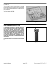
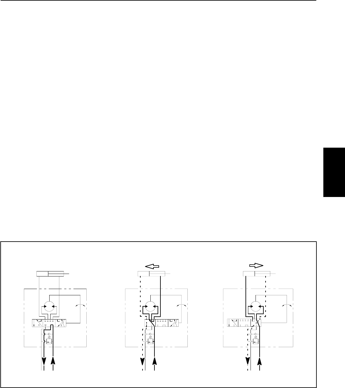
With the steering wheel in the neutral position and the
engine running, pump section P3 flow enters the steer-
ing control valve at the P port and goes through the
steering control spoolvalve, bypassing the rotary meter
(V1) andsteering cylinder.Flow leaves thecontrol valve
through the PB port to the oil filter and traction charge
circuit.
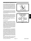
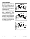
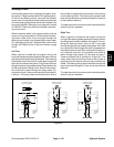
Left Turn
When a left turn is made with the engine running, the
turningofthesteeringwheelpositionsthe spool valveso
thatflowgoes throughthetopof thespool.Flowentering
the steering control v alve at the P port goes through the
spool and is routed to two places. First, most of the flow
throughthevalveisbypassedoutthePBportbacktothe
oil filter and traction charge circuit. Second, the remain-
der of the flow is drawn through the rotary meter (V1)
and outthe L port.Pressure contracts the liftcylinder for
a left turn. The rotary meter ensures that the oil flow to
the cylinder is proportional to the amount of the turning
on the steering wheel. Fluid leaving the cylinder flows
backthroughthe spoolvalve then throughtheT portand
to the hydraulic reservoir.
The steeringc ontrol valve returns to the neutralposition
when turning is completed.
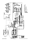
Right Turn
When a right turn is made with the engine running, the
turningofthesteeringwheelpositionsthe spool valveso
that flow goes through the bottom of the spool. Flow en-
tering the steering control valve at the P port goes
through thespool andis routed totwo places.As ina left
turn, most of the flow through the valve is bypassed out
the PB port back to the oil filter and traction charge cir-
cuit. Also like a left turn, the remainder of the flow is
drawn through rotary meter (V1) but goes out port R.
Pressure extends the lift cylinder for a right turn. The
rotary meter ensures that the oil flow to the cylinder is
proportional to the amount ofthe turning on the steering
wheel. Fluid leaving the cylinder flows back through the
spool valve then through the T port and to the hydraulic
reservoir.
The steeringc ontrol valve returns to the neutralposition
when turning is completed.
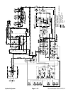
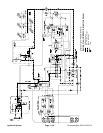
Figure 23
1050
PSI
PB
STEERING
T
R
P
L
PISTONMOVEMENT
CONTROL
1050
PSI
PB
STEERINGCYLINDER
T
R
P
L
PISTONMOVEMENT
1050
PSI
PB
STEERINGCYLINDER
T
R
P
L
LEFT TURN
NEUTRAL POSITION
RIGHT TURN
NOPISTONMOVEMENT
STEERINGCYLINDER
VALVE
STEERING
CONTROL
VALVE
STEERING
CONTROL
VALVE
Hydraulic
System