


Groundsmaster 4500--D/4700--DPage 6 -- 22Axles, Planetaries and Brakes
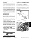
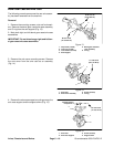
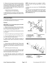
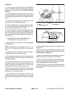
9. Remove the bevel gear case/axle case assembly
from the axle support. Coat a new O-ring with grease
andtemporarilyinstall the axlecover assembly.Position
a dial indicator at the tooths center. Prevent the axle
from turning and measure the lower bevel gear to axle
gear backlash (Fig. 22).
LOWER BEVEL GEAR BACKLASH:
0.004 to 0.016 in. (0.10 to 0.40 mm)
10.Adjust backlashby increasingor reducingaxle bear-
ingshim thickness(see AxleShaftsin thissection ofthis
manual).
NOTE: Axle bearing shims are available in 0.008 in.
(0.2 mm), 0.012 in. (0.3 mm) and 0.020 in. (0.5 mm)
thickness.
11.Tighten axle cover screws from 17 to 20 ft-lb (23 to
27 N--m).
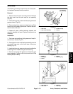
12.Coat a new O-ring with grease and install the bevel
gear case/axle case assembly on the axle support.
Tighten mounting screws and nuts from 35 to 41 ft-lb
(47to56N--m)(Fig. 13).
Differential Shafts
The following procedures assume the rear axle assem-
bly has been removed from the machine.
Removal
IMPORTANT: Do not interchange right and left dif-
ferential shaft assemblies.
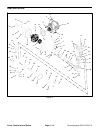
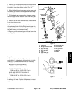
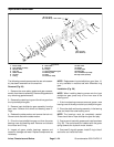
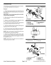
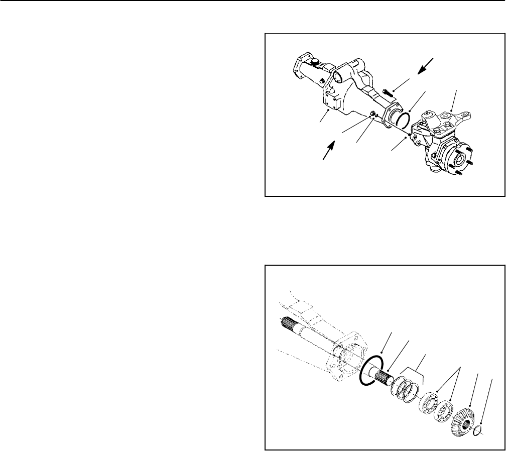
1. Remove the mounting screws, nuts and lock wash-
ers. Remove the bevel gear case/axle case assembly
and O-ring from the axle s upport (Fig. 23).
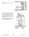
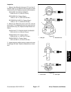
2. Markandpull thedifferentialshaftassembly fromthe
axle support.
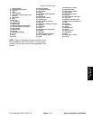
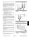
3. Remove the r etaining ring and bevel gear (Fig 24).
4. Drive the differential shaft out of the bearings. Re-
move the bearings and bearing shims.
5. Inspect all gears, shafts, bearings and cases for
damage and wear. Replace components as necessary.
Installation
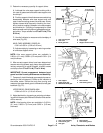
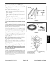
1. Press bearings onto differential shaft. Place correct
combination of bearing shims in axle support and drive
differential shaft and bearing assembly into axle sup-
port.
2. Install bevel gear and retaining ring.
3. Coat new O-ring with grease. Align differential shaft
splines with differential gear assembly and slide differ-
ential shaft assembly onto axle support.
4. Install bevel gear case/axle case assembly (see
Bevel Gear Case/Axle Case Assembly in this section of
this manual).
1
2
3
4
5
6
1. Cap screw (4 used)
2. Lock nut (2 used)
3. Lock washer (2 used)
4. Axle support
5. Bevel gear/axle case
assembly
6. O-ring
7. Stud (2 used)
Figure 23
7
35 to 41 ft--lb
(47to56N--m)
35 to 41 ft--lb
(47to56N--m)
1
2
3
4
5
6
1. Retaining ring
2. Bevel gear
3. Differential shaft
4. Bearing
5. Bearing shims
6. O-ring
Figure 24