


Groundsmaster 4500--D/4700--D Hydraulic SystemPage 4 -- 119
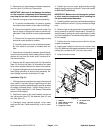
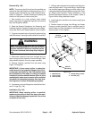
WARNING
Make sure that cutting decks are fully lowered
before loosening hydraulic lines from lift man-
ifold. If decks are raised as hydraulic lines are
loosened, decks may drop unexpectedly.
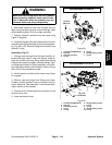
6. Disconnect hydraulic lines from manifold and put
caps or plugs on open hydraulic lines and fittings. Label
disconnected hydraulic lines for proper assembly.
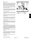
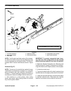
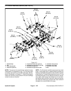
7. Remove hydraulic manifold from the frame using
Figure 97 as guide.
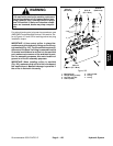
8. If hydraulic fittings areto be removed from lift control
manifold,mark fittingorientation toallowcorrect assem-
bly (Fig. 98 or 99). Remove fittings from manifold and
discard O--rings.
Installation (Fig. 97)
1. If fittings were removed from lift control manifold, lu-
bricate and place new O--rings onto fittings. Install fit-
tings into manifold openings using marks made during
the removal process to properly orientate fittings. Tight-
en fittings (see Hydraulic Fitting Installation in the Gen-
eral Information section of this chapter). Refer to Figure
98 or 99 for fitting installation torque.
2. Install hydraulic manifold to the frame using Figure
97 as guide.
3. Remove caps and plugs from fittings and hoses.
Properly connect hydraulic lines to manifold (see Hy-
draulic Hose and Tube Installation in the General Infor-
mation section of this chapter).
4. Connect wire harness electrical connectors to the
solenoid valve coils.
5. Lower and secure hood.
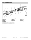
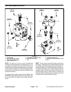
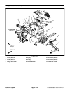
1. Lift manifold (GM4500--D)
2. Dust cap
3. Test fitting (2 used)
4. O--ring
5. O--ring
6. Straight fitting (2 used)
7. O--ring
Figure 98
4
3
2
1
5
6
7
GROUNDSMASTER 4500--D
6
3
50 ft--lb
(68 N--m)
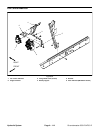
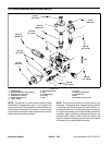
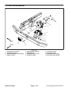
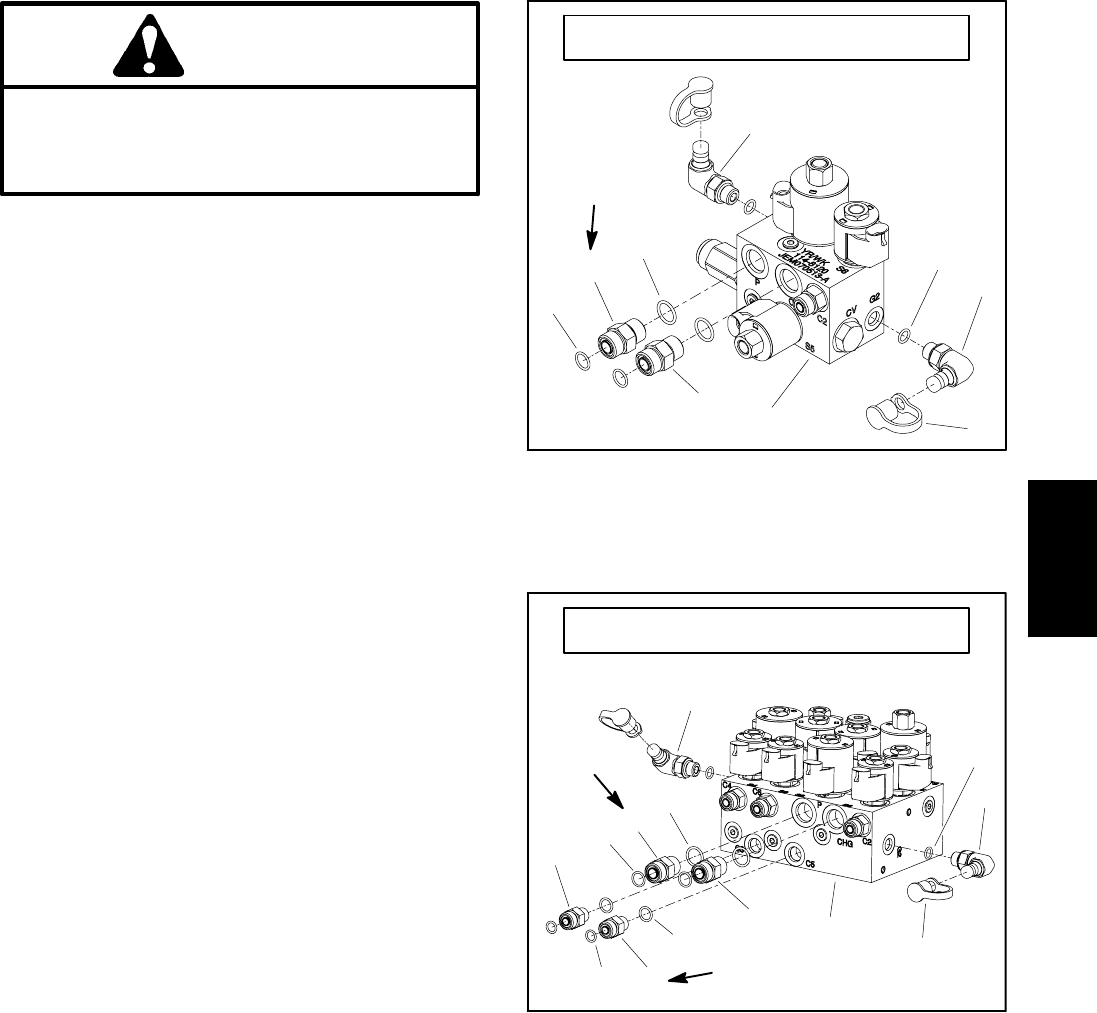
1. Lift manifold (GM4700--D)
2. Dust cap
3. Test fitting (2 used)
4. O--ring
5. O--ring
6. Straight fitting (2 used)
7. O--ring
8. O--ring
9. Straight fitting (2 used)
10. O--ring
Figure 99
GROUNDSMASTER 4700--D
4
3
2
1
5
6
7
3
6
8
9
10
9
50 ft--lb
(68 N--m)
25 ft--lb
(33.9 N--m)
Hydraulic
System