


Groundsmaster 4500--D/4700--D Hydraulic SystemPage 4 -- 49
NOTE: When inreverse, pressure reducing valve (PR)
limits the pressure to the rear axle motor to 450 PSI (31
bar) so the rear wheels will not scuff the turf.
Procedure for Traction Circuit Pressure Reducing
Valve (PR) Pressure Test
1. Make sure hydraulic oil is at normal operating tem-
peraturebyoperatingthemachineforapproximatelyten
(10) minutes. Make sure the hydraulic tank is full.
2. Park machine on a level surface with the cutting
decks lowered and off. Make sure engine is off and the
parking brake is engaged.
CAUTION
Prevent personal injury and/or damage to equip-
ment. Read all WARNINGS, CAUTIONS and Pre-
cautions for Hydraulic Testing at the beginning
of this section.
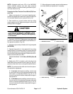
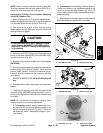
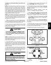
3. Connect a 1000 PSI (70 bar) pressure gauge to test
port G on rear side of 4WD/2WD control manifold under
operator’s platform (Fig. 38).
4. Start the engine and put throttle at full engine speed
(2870 RPM).
5. Siton seat,apply brakesfully andslowly depressthe
traction pedal in the reverse direction. While pushing
traction pedal, carefully monitor the pressure gauge.
Pressure should increase until the pressure reducing
valve opens.
GAUGEREADINGTOBE420 to 470 PSI (29 to 32
bar).
6. Release traction pedal, stop engine and record test
results.
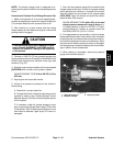
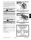
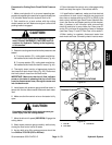
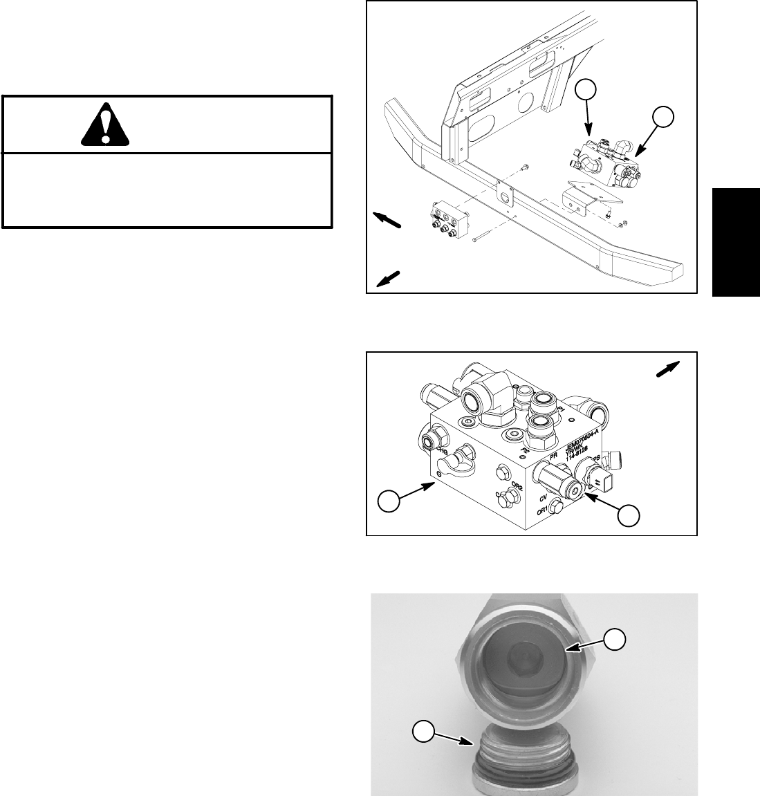
7. The pressure reducing valve (PR) is located on the
right side of the 4WD/2WD control manifold in the PR
port(Fig. 39).Adjustment ofthis valvecanbe performed
as follows:
NOTE: Do not remove the pressure reducing valve
from the hydraulic manifold for adjustment.
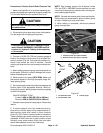
A. To increase pressure setting, remove cap on re-
ducing valve and turn the adjustment socket on the
valve in a clockwise direction (Fig. 40). A 1/8 turn on
the s ocket will make a measurable change in pres-
sure setting.
B. To decreasepressure setting,remove cap onre-
ducing valve and turn the adjustment socket on the
valve in a counterclockwise direction (Fig. 40). A 1/8
turn on thesocket will make ameasurable change in
pressure setting.
C. Afteradjustment ismade, recheckr elief pressure
and make additional adjustment if necessary.
1. 4WD/2WD manifold 2. Reducing valve (PR)
Figure 38
1
2
FRONT
RIGHT
1. 4WD/2WD manifold 2. Reducing valve (PR)
Figure 39
1
2
FRONT
Figure 40
1. Reducing valve cap 2. Adjustment socket
1
2
Hydraulic
System