


Groundsmaster 4500--D/4700--D Page 7 -- 13 Chassis
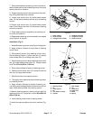
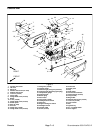
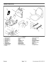
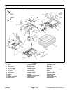
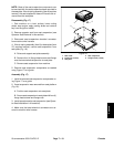
Removal (Fig. 12)
1. Park machine on a level surface, lower cutting
decks, stop engine, engage parking brake and remove
key from the ignition switch.
2. Remove cutting deck from lift arm (see Cutting Deck
Operator’s Manual).
3. Remove pin (item 27) that secures lift links (item 10)
to lift arm.
4. Loosen and remove lock nut (item 19) from pivot pin
(item 28).
5. Support lift armand pull lift arm pivot pin from liftarm
and support arm. Locate and remove thrust washer
(item 20) from rear of lift arm during pivot pin removal.
6. Remove lift arm from machine.
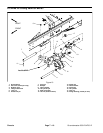
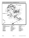
7. Disassemble lift arm as needed using Figure 12 as
a guide.
8. Clean lift arm and pivot pin. Inspect lift arm bushings
and pivotpin fordamage orwear. Replaceworn ordam-
aged components.
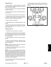
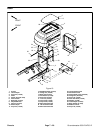
Installation (Fig. 12)
1. Assemble lift arm using Figure 12 as a guide.
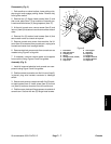
2. Position lift arm to support arm. Fit thrust washer
(item 20) betweenrear of lift arm andsupport arm. Slide
pivotpinintosupport armandliftarm. Align rollpin inpiv-
ot pin with slot in support arm flange.
3. Install andtighten locknut (item 19)to secure liftarm
pivot pin.
4. Secure liftlinks (item 10)to lift arm withpin (item 27).
Make sure that thrust washer (item 15) and retaining
ring (item 1) are on both ends of pin.
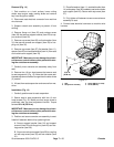
NOTE: Install compression spring (item 23) and thrust
washer (item 24) on carrier pivot pin before installing
cutting deck on pivot pin.
5. Position and install cutting deck to lift arm (see Cut-
ting Deck Operator’s Manual).
6. Lubricate lift arm grease fittings after assembly is
complete.
7. After assembly, raise and lower the cutting deck to
verify that hydraulic hoses and fittings do not contact
anything.
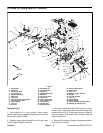
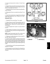
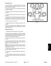
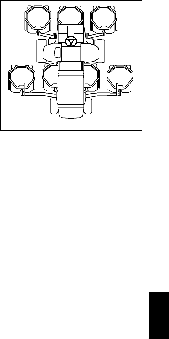
Figure 13
#4 Deck #1 Deck #5 Deck
#7 Deck
(GM4700)
#6 Deck
(GM4700)
#3
Deck
#2
Deck
CUTTING DECK LOCATIONS
Chassis