


Groundsmaster 4500--D/4700--DPage 5 -- 20Electrical System
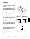
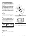
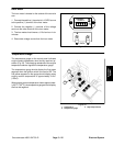
Hi--Low Speed and Headlight Switches
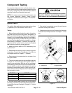
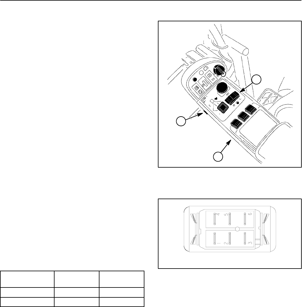
The Hi--Low speed switch is locatedon the console arm
(Fig.23). Thistwo positionrocker switchallows the trac-
tion speed to be set to high speed (transport) or low
speed (mow).
The headlight switch is located on the operator side of
the console arm (Fig. 23). This two position rocker
switch allows the headlights to be turned on and off.
NOTE: Before disconnecting the Hi--Low speed switch
for testing, the switch and its circuit wiring should be
tested as a TEC input with the Diagnostic Display (see
DiagnosticDisplay inthe Troubleshootingsectionof this
chapter).
Testing
1. Make sure ignition switch is OFF. Remove key from
ignition switch.
2. Disassemble console arm to gain access to switch
thatisto betested (seeConsole Arm Disassemblyinthe
Service and Repairs section of C hapter 7 -- Chassis).
3. Disconnect harness electrical connector from the
switch.
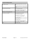
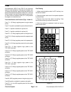
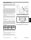
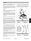
4. With the use of a multimeter (ohms setting), the
switch functions may be tested to determine whether
continuity exists between thevarious terminals for each
switch position. The switch terminals are marked as
shown in Figure 24. The circuitry of the switch is shown
in the chart below. Verify continuity between switch ter-
minals. Replace switch if testing identifies a faulty
switch.
SWITCH
POSITION
CIRCUIT 1 CIRCUIT 2
ON 2+3 5+6
OFF 2+1 5+4
5. If switch tests correctly and circuit problem still ex-
ists, checkwire harness (see Electrical Schematics and
Wire Harness Drawings in Chapter 9 -- Foldout Draw-
ings).
6. After testing is completed, connect wire harness
connector to the switch.
7. Assemble consolearm (see Console Arm Assembly
in the Service and Repairssection of Chapter 7 -- Chas-
sis).
1. Console arm
2. Hi--Low speed switch
3. Headlight switch
Figure 23
1
2
3
Figure 24
BACK OF SWITCH
NOTE: Switch terminals 1, 4, 5 and 6 are not used on
Groundsmaster 4500--D and 4700 --D machines.