


Groundsmaster 4500--D/4700--DHydraulic System Page 4 -- 116
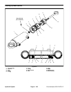
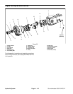
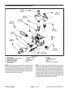
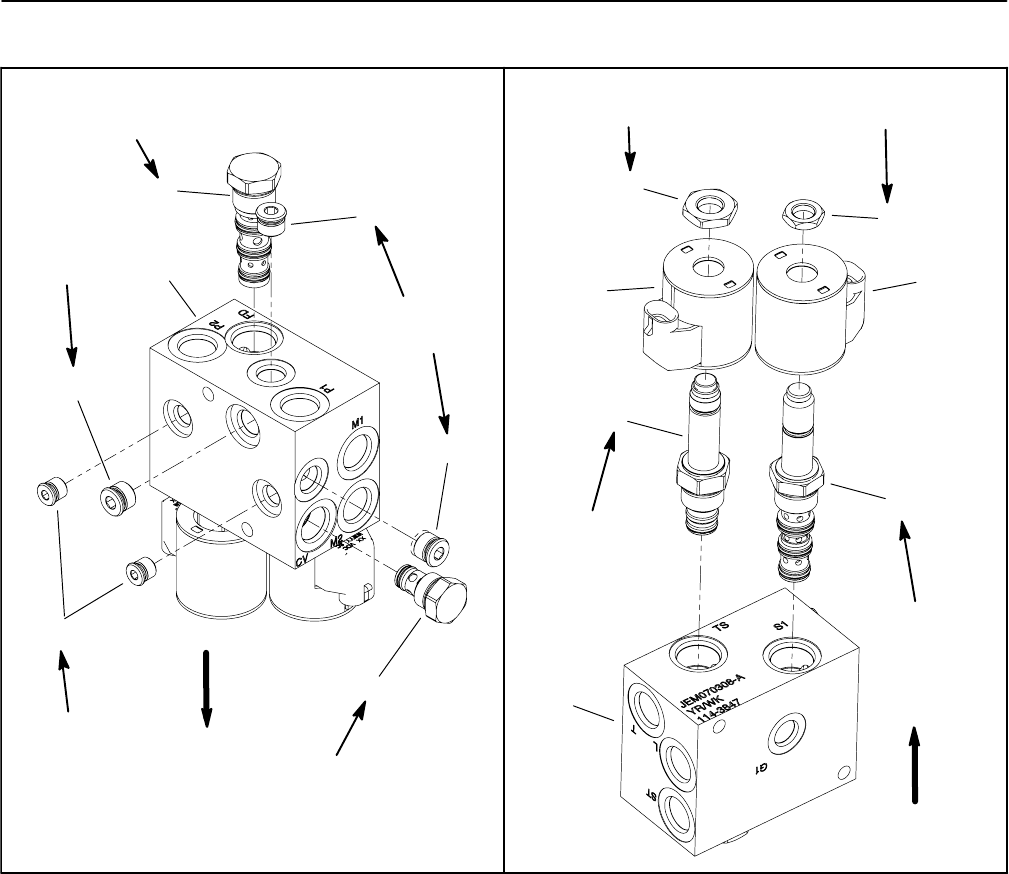
Fan Control M anifold Service
1. Manifold body
2. Zero leak plug (#6) (3 used)
3. Zero leak plug (#4) (2 used)
4. Check valve (port CV)
5. Flow divider cartridge (port FD)
6. Solenoid coil (2 used)
7. Nut
8. Solenoid valve (port S1)
9. Proportional relief cartridge (port TS)
10. Nut
Figure 96
7
4
6
3
2
1
5
9
8
2
2
6
25 ft--lb
(33.9 N--m)
25 ft--lb
(33.9 N--m)
20 ft--lb
(27.1 N--m)
5 ft--lb
(6.8 N--m)
20 ft--lb
(27.1 N--m)
25 ft--lb
(33.9 N--m)
25 ft--lb
(33.9 N--m)
5 ft--lb
(6.8 N--m)
1
10
UP
UP
50 ft--lb
(68 N--m)
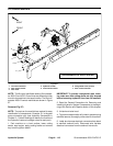
NOTE: The ports on the fan control manifold are
marked foreasy identification of components (e.g.ST is
the supply to the steering control valve and FD is the
locationof theflow dividercartridgevalve). SeeHydrau-
licSchematicsinChapter 9-- FoldoutDrawingstoidenti-
fy thefunctionof thehydraulic lines andcartridge valves
at each port location.
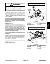
For solenoid and control valve service procedures, see
4WD/2WD Control Manifold Service in this section. Re-
fer to Figure 96 for cartridge valve and plug installation
torque.
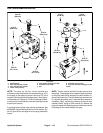
NOTE: The fan control manifold includes several zero
leak plugs. These plugs have a tapered sealing surface
on the plug head that is designed to resist vibration in-
duced plug loosening.The zero leak plugs alsohave an
O--ring as a secondary seal. If zero leak plug removal is
necessary, lightly rap the plug head using a punch and
hammer before using an allen wrench to remove the
plug:the impactwill allowplug removalwith lesschance
of damage to the socket head of the plug.