


Groundsmaster 4500--D/4700--D Page 6 -- 21 Axles, Planetaries and Brakes
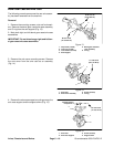
5. Determine necessary quantity of support shims.
A. Lubricate the axle case support bushing with a
thin coat of grease and slide axle case support onto
knuckle pin.
B. Positionsupport shimsthat wereremoved during
disassembly between axle case support and axle
case. Install mounting screws into axle case. Slowly
tighten screws while frequently checking for clear-
ance (vertical endplay) between axle case support
and knuckle pin. If binding of components is noted
beforescrewsarefullytightened,addadditionalsup-
port shims. Torque screws from 57 to 67 ft--lb (77 to
91 N--m).
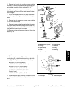
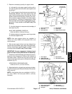
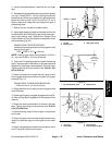
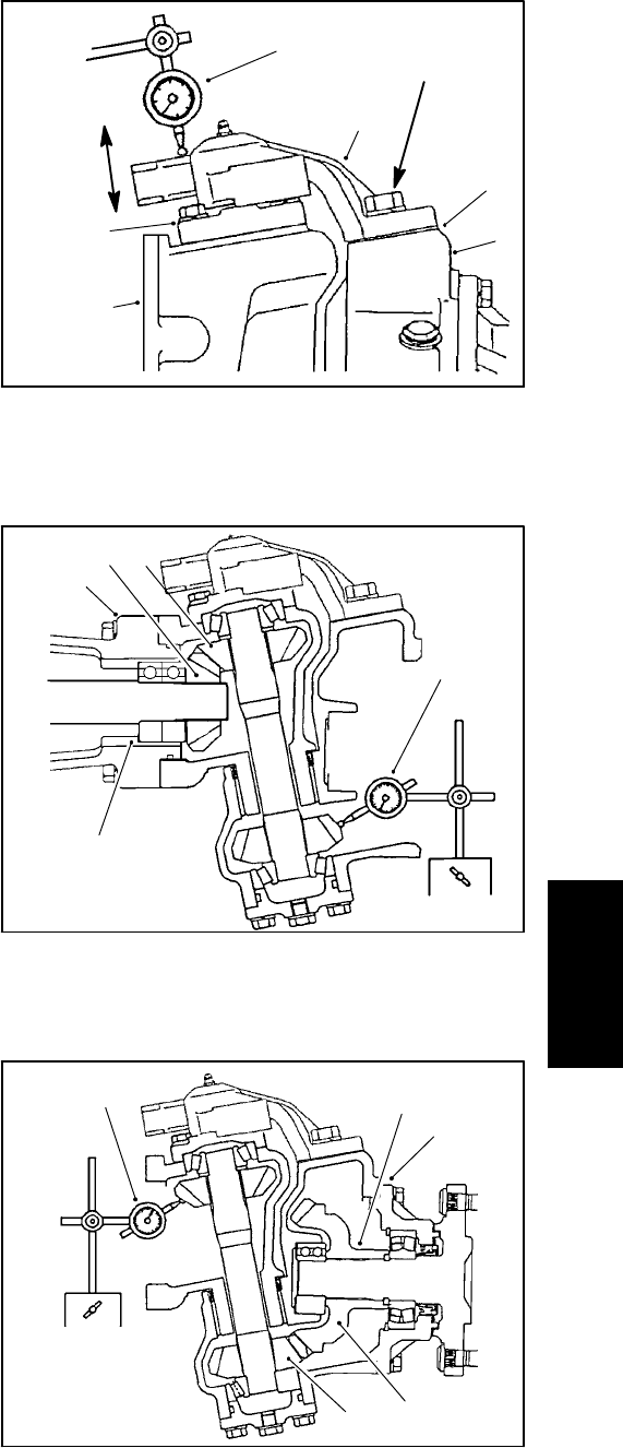
C. Use dial indicator to measure vertical endplay of
axle case (Fig. 20).
AXLE CASE ASSEMBLY ENDPLAY:
0.001 to 0.008 in. (0.02 to 0.20 mm)
D. Adjustendplay byincreasing orreducing number
of axle case support shims.
NOTE: Axle case support shims are available in
0.004 in. (0.1 mm), 0.008in. (0.2 mm) and0.016 in. (0.4
mm) thickness.
6. After correct support shims have been determined,
removemounting screws,apply heavystrengththread--
locking compound to screw threads, reinstall screws
and torque from 57 to 67 ft--lb (77 to 91 N--m).
IMPORTANT: Correct engagement between bevel
gears is critical to axle performance and durability.
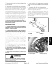
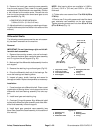
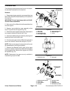
7. Temporarilyinstall thebevel gear case/axlecase as-
sembly on the axle support. Position a dial indicator at
the tooths center. Prevent the axle from turning and
measure the upper bevel gear to differential shaft gear
backlash (Fig. 21).
UPPER BEVEL GEAR BACKLASH:
0.004 to 0.016 in. (0.10 to 0.40 mm)
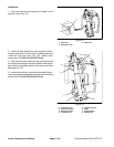
8. Adjustbacklash byincreasing orreducing axlebear-
ingshim thickness(see DifferentialShafts inthissection
of this manual).
NOTE: Axle bearing shims are available in 0.004 in.
(0.1 mm), 0.008 in. (0.2 mm) and 0.020 in. (0.5 mm)
thickness.
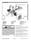
1. Axle case support
2. Axle case
3. Bevel gearcase
4. Dial indicator
5. Knuckle pin
6. Support shim location
Figure 20
1
2
4
5
3
6
VERTICAL
ENDPLAY
57 to 67 ft--lb
(77to91N--m)
1
2
3
4
5
1. Axle support
2. Upper bevel gear
3. Differential shaft gear
4. Dial indicator
5. Axle bearing shims
Figure 21
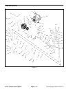
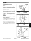
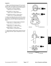
1. Axle cover assembly
2. Lower bevel gear
3. Axle gear
4. Dial indicator
5. Axle bearing shims
Figure 22
1
2
3
4
5
Axles, Planetaries
and Brakes