


Groundsmaster 4500--D/4700--D Cutting DecksPage 8 -- 13
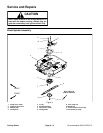
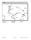
Removal (Fig. 9)
1. Park machine on a level surface, lower cutting
decks, stop engine, engage parking brake and remove
key from the ignition switch.
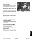
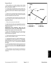
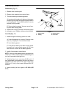
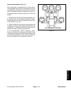
2. If cutting deck is equipped with a roller scraper (Fig.
10),removefastenerssecuring leftandrightscraperrod
brackets to roller mounts. Remove scraper rod assem-
bly.
3. Remove four (4) flange head screws securing roller
mountstorearofdeckframe. Remove rollermountsand
rear roller assembly from deck frame.
4. Loosenfasteners securingeachend ofroller toroller
mounts. Remove mounts and skid brackets from roller.
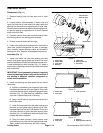
Installation (Fig. 9)
1. Slide roller mounts onto roller shaft.
2. Install roller and roller mount assembly into rear of
deckframe.Secureassemblytodeckframewith four(4)
flange head screws.
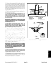
IMPORTANT: During assembly, make sure the
grease groove in each roller mount aligns with the
grease hole in each end of the roller shaft.
3. Align roller shaft grease hole with the roller mount
grease groove. Use alignment mark on end of roller
shaft to assist with alignment.
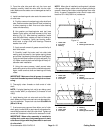
4. Positionskidbrackets torollermountsandinstallcap
screws to retain brackets in place.
5. Ifequippedwith scraperrod, installand adjustscrap-
er rod assembly to roller mounts (Fig. 10). The gap be-
tween the scraper rod and roller should be from 0.020
to 0.040 in (0.5 to 1.0 mm). Torque cap screws 30 ft--lb
(41 N--m).
6. Install and tighten fasteners that secure each end of
roller to roller mounts. Torque roller shaft screws (item
4) and cap screws ( item 8) from 29 to 35 ft--lb (40 to 47
N--m).
7. After assembly, raise and lower the cutting deck to
verify that hydraulic hoses and fittings do not contact
anything.
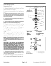
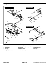
1. Grease fitting
2. Roller shaft screw
3. Scraper plate
4. Cap screw
5. Roller scraper
6. Roller mount
Figure 10
3
5
4
2
1
6
29 to 35 ft--lb
(40to47N--m)
30 ft--lb
(41 N--m)
Cutting Decks