


Groundsmaster 4500--D/4700--D Hydraulic SystemPage 4 -- 25
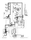
Mow Circuit
Hydraulic flow for the mow circuit is supplied by two (2)
sections ofthe gear pump(P1 andP2). Gear pumpsec-
tion P1 supplies hydraulic flow to decks 5, 3 and 2 (also
deck 7on the GM4700--D), while gear pumpsection P2
suppliesdecks 1and 4(also deck6 onthe GM4700--D).
A single deck control manifold is used to control flow
from the two (2) pump sections. The manifold includes
cartridge valves for control of each of the two (2) pump
circuits. Each manifold circuit is equipped with a sole-
noid controlled, proportional relief v alve (PRV1/PRV2),
a logic cartridge (LC1/LC2) and a brake relief cartridge
(RV8/RV9). TheGroundsmaster 4700--D deckmanifold
includes additional cartridges to control hydraulic flow
for decks 6 and 7: an additional logic cartridge
(LC3/LC4),asolenoid valve(SV1/SV2)and anaddition-
al brake relief cartridge (RV10/RV11).
PTO Disengaged
When thePTOswitch isOFF (orif thedecks areraised),
the manifold solenoid valves (PRV1 and PRV2) are not
energized, allowing hydraulic flow to bypass the deck
motors through the manifold. Return oil from the man-
ifolds is directed to the oil cooler and oil filter.
PTO Engaged
When the PTO switch is turned ON with the decks low-
ered, the solenoid valves (PRV1 and PRV2) are ener-
gized with outputs from the TEC--5002 controller. The
energized valves shift to direct pump flow toward the
deck motors. As circuit pressure to the deck motors in-
creases, the brake relief cartridge (RV) opens which al-
lows an oil flow through the manifold orifice positioned
before the logiccartridge (LC). This flow creates apres-
sureincrease atthe logiccartridgethat willshift thelogic
cartridge and allow oil return from the deck motors.
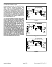
On the Groundsmaster 4700--D (Fig. 19), if deck 6 or
deck 7 is lowered and the PTO switch is ON, the deck
control manifold solenoid valve (SV1/SV2) will be ener-
gized by the TEC--5001 controller. This energized sole-
noid valve allows oil flow to the appropriate deck motor
as described above.
Maximum mow circuit pressure is limited at each deck
manifold circuit by the proportional relief valve
(PRV1/PRV2). The deck relief valve pressure is 3500
PSI (241bar). Mowcircuit pressure canbe measuredat
port G1 or G3 of the deck control manifold.
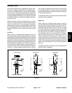
Thebrakereliefand logiccartridges controlthestopping
rate of the blades when the solenoid v alves are de--en-
ergized as the PTO switch is turned OFF or if the decks
are raised (see Cutting Deck Blade Braking in this sec-
tion).
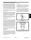
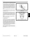
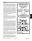
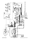
Figure 18
#4 Deck #1 Deck #5 Deck
#7 Deck
(GM4700)
#6 Deck
(GM4700)
#3
Deck
#2
Deck
CUTTING DECK LOCATIONS
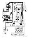
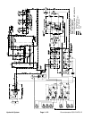
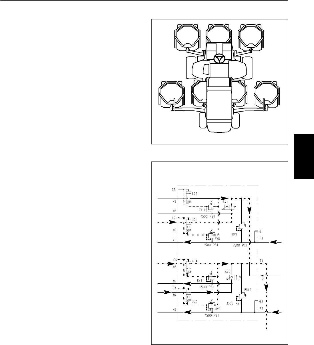
Figure 19
DECK CONTROL MANIFOLD
FROM
(Groundsmaster 4700--D)
FROM
TO DECKS
FROM
1&4
DECKS
1&4
TO DECKS
2,3 &5
TO DECK
6
FROM
DECK 6
FROM
DECKS
2,3 &5
TO DECK
7
FROM
DECK 7
PUMPP1
PUMPP2
TO OIL
COOLER
PTO SWITCH ON AND
#7 (RH) DECK RAISED
Hydraulic
System