


Groundsmaster 4500--D/4700--DPage 5 -- 24Electrical System
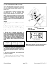
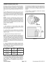
Cutting Deck Position Switch
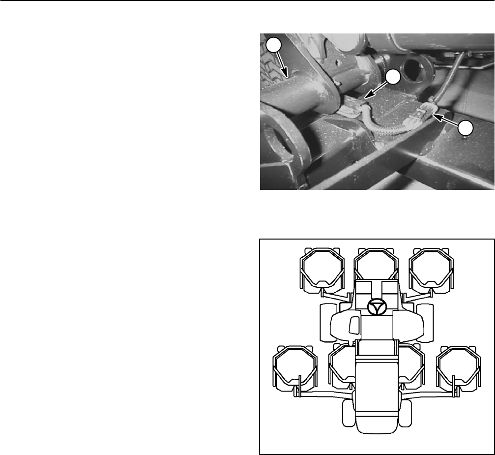
Thecuttingdeckpositionswitchis anormallyopenprox-
imityswitchthat islocatedon the tractionunitframe(Fig.
30). The sensing plate is located on the cutting deck lift
arm. The Groundsmaster 4500--D uses two (2) cutting
deckposition switches:for decks4 and5. Thereare four
(4) deck position switches on the Groundsmaster
4700--D: for decks 4, 5, 6 and 7.
When a cutting deck is lowered, the sensing plate is lo-
cated near the position switch and the switch closes.
Thisclosedswitch providesaninput fortheTEC control-
ler to allow the lowered cutting decks to operate.
Switch Testing
1. Park machine on a level surface, lower cutting
decks, stop engine and engage parking brake.
2. Before disconnecting the cutting deck position
switch for testing, theswitch and its circuit wiring should
be tested as a TEC input with the Diagnostic Display
(see Diagnostic Display in the Troubleshooting section
ofthis chapter).If theDiagnosticDisplayverifies thatthe
positionswitchand circuitwiringarefunctioningcorrect-
ly,no further switchtesting isnecessary. If,however,the
Display determines that the position switch and circuit
wiring are not functioning correctly, proceed with test.
3. Make sure ignition switch is OFF. Remove key from
ignition switch.
4. Disconnectdeckposition switchthat requirestesting
from machine wire harness.
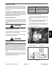
5. Check the continuity of the switch by connecting a
multimeter (ohms setting) across the switch connector
terminals.
6. With the cutting deck in the lowered position, there
should be continuity across the switch terminals.
7. Raisethecuttingdeck.Theres hould benocontinuity
across the switch terminals.
8. Replace position switch if testing determines that it
is faulty.
9. After testing is complete, connectwire harness elec-
trical connector to the position switch.
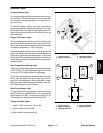
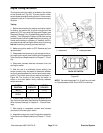
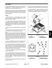
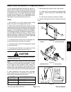
Switch Adjustment
1. Adjust switchto have 1/16 in (1.6 mm)clearance be-
tween switch and sensing plate on the lift arm.
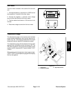
1. Position switch
2. Switch connector
3. Lift arm (#5 shown)
Figure 30
2
1
3
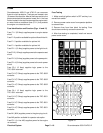
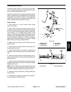
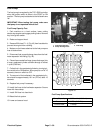
Figure 31
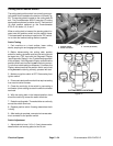
#4 Deck #1 Deck #5 Deck
#7 Deck
(GM4700)
#6 Deck
(GM4700)
#3
Deck
#2
Deck
CUTTING DECK LOCATIONS