


Groundsmaster 4500--D/4700--DPage 6 -- 8Axles, Planetaries and Brakes
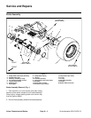
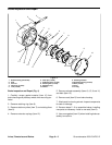
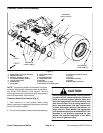
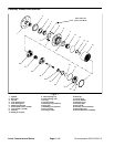
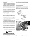
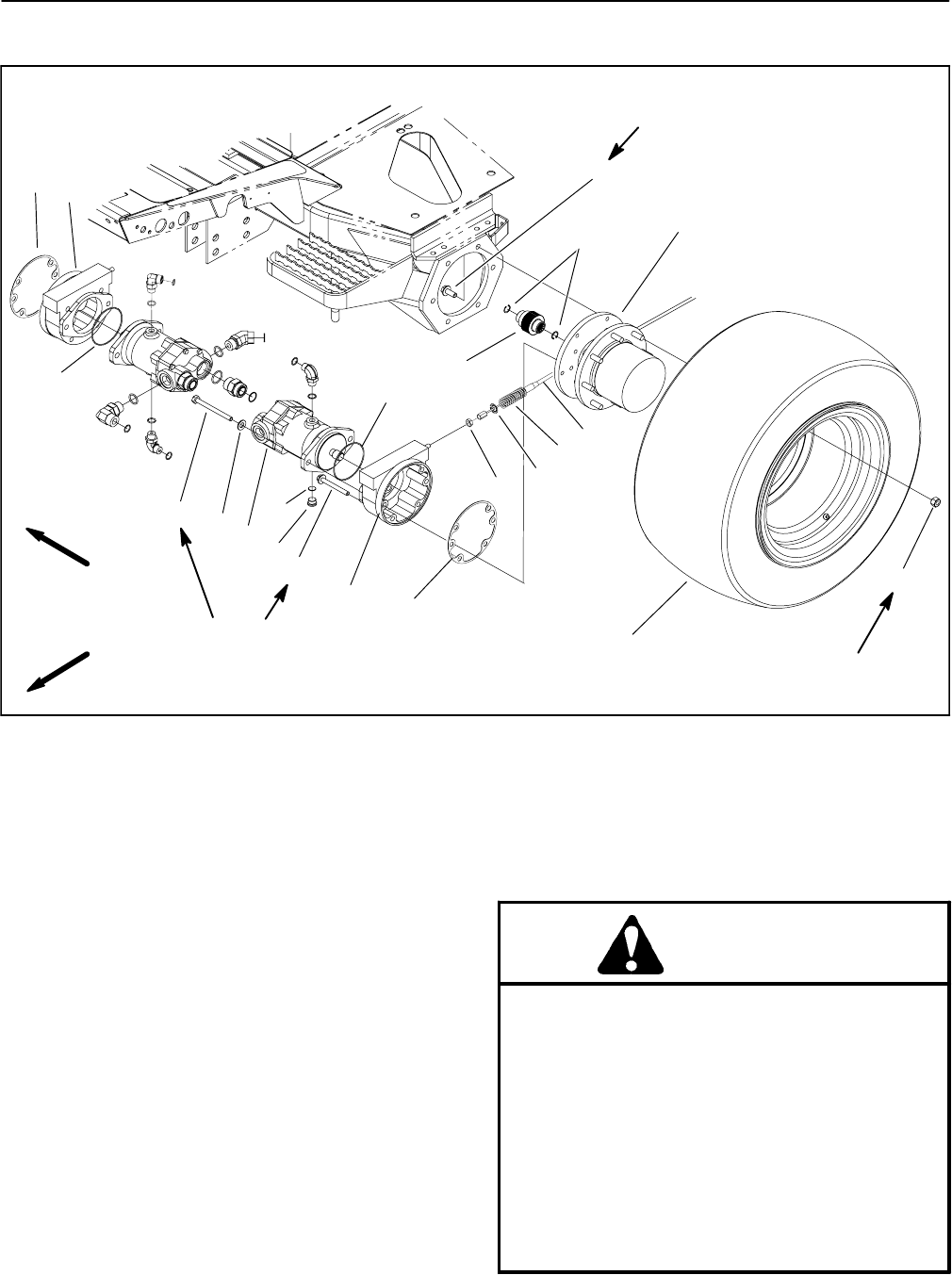
Planetary Wheel Drive Assembly
1. Flange head screw (6 per planetary)
2. Splined brake shaft
3. Planetary assembly (2 used)
4. Front wheel assembly (2 used)
5. Lug nut (8 per wheel)
6. Retaining ring
7. Spring plate
8. Compression spring
9. Jam nut
10. LH Brake assembly
11. Flange head screw
12. Hex plug
13. Piston motor (2 used)
14. Flat washer (2 used per motor)
15. Cap screw (2 used per motor)
16. O--ring
17. O--ring
18. RH brake assembly
19. Gasket
20. Brake cable (LH shown)
Figure 5
75 to 85 ft--lb
(102 to 115 N--m)
85 to 100 ft--lb
(116 to 135 N--m)
1
2
3
4
5
6
7
8
9
10
11
12
13
14
15
17
18
16
17
75 to 85 ft--lb
(102 to 115 N--m)
FRONT
RIGHT
19
19
20
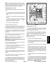
NOTE: Theplanetarywheeldriveassemblycanbeser-
vicedwiththeplanetaryinstalledtomachine(seePlane-
tary Wheel Drive Service in this section). Use the
following procedure to remove and install the planetary
wheel drive assembly from machine.
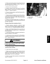
Planetary Wheel Drive Removal (Fig. 5)
1. Park machine on a level surface, lower cutting
decks, stop engine, engage parking brake and remove
key from the ignition switch.
2. Drainoil fromplanetary wheeldrive/brake assembly.
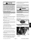
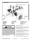
CAUTION
When changing attachments, tires or perform-
ingother service,use correctblocks, hoistsand
jacks to raise and support machine. Make sure
machine is parked on a solid level surface such
as a concrete floor. Prior to raising machine, re-
move any attachments that may interfere with
the safe and proper raising of the machine. Al-
ways chock or block wheels. Use appropriate
jack standsto support theraised machine. Ifthe
machine is not properly supported by jack
stands, the machine may move or fall, which
may result in personal injury.