


Groundsmaster 4500--D/4700--DHydraulic System Page 4 -- 98
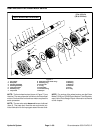
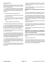
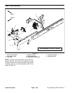
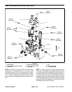
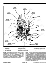
Deck Control Manifold Service (GM 4500--D)
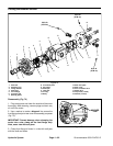
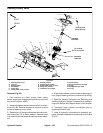
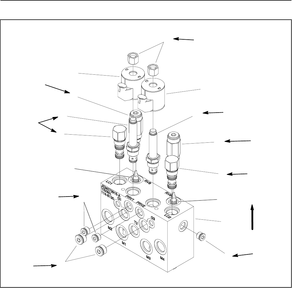
1. Manifold body
2. Proportional relief (PRV1 & PRV2)
3. Solenoid coil
4. Relief valve (RV8 & RV9)
5. Logic valve (LC1 & LC2)
6. Pilot piston
7. Nut
8. Zero leak plug (#6)
9. Zero leak plug (#8)
Figure 81
1
3
4
5
6
7
9
8
2
3
2
4
5
6
8
5 ft--lb
(6.8 N--m)
25 ft--lb
(33.9 N--m)
20 ft--lb
(27.1 N--m)
25 ft--lb
(33.9 N--m)
25 ft--lb
(33.9 N--m)
25 ft--lb
(33.9 N--m)
25 ft--lb
(33.9 N--m)
20 ft--lb
(27.1 N--m)
UP
50 ft--lb
(68 N--m)
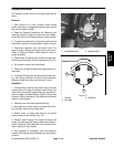
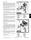
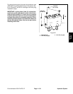
NOTE: The ports on the manifold are marked for easy
identification of components (e.g. P1 is a gear pump
connection port and PRV1 is the location for a propor-
tional relief valve). See Hydraulic Schematics in Chap-
ter 9 -- Foldout Drawings to identify the function of the
hydraulic lines and cartridge valves at each port loca-
tion.
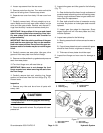
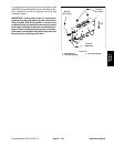
NOTE: The deck control manifold uses several zero
leak plugs. These plugs have a tapered sealing surface
on the plug head that is designed to resist vibration in-
duced plug loosening.The zero leak plugs alsohave an
O--ring as a secondary seal. If zero leak plug removal is
necessary, lightly rap the plug head using a pin punch
andhammerbeforeusinganallen wrench to removethe
plug:the impactwill allowplug removalwith lesschance
of damage to the head of the plug.