


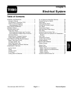

Groundsmaster 4500--D/4700--D Page 5 -- 7 Electrical System
5. The “inputs displayed
” LED,on lower rightcolumn of
theDiagnostic Display, shouldbe illuminated.If“
outputs
displayed
”LEDisilluminated,pressthe togglebuttonon
the Diagnostic D isplay to change to “inputs displayed
”
LED.
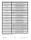
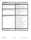
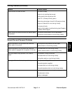
6. The Diagnostic Display will illuminate the LED
associatedwitheachoftheinputswhenthatinputswitch
is closed.Individually, changeeach ofthe switchesfrom
open to closed (i.e., sit on seat, press traction pedal,
etc.),and notethat theappropriate LEDon theDiagnos-
ticDisplay willilluminate whenthe correspondingswitch
is closed. Repeat on each switch that is possible to be
changed by hand (see Inputs and LED Operation c hart
on following page).
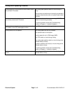
NOTE: When the Diagnostic Display is attached to the
wire harness connector and the ignition switch is in the
ONposition,theinputLEDfortractionpressure,hydrau-
lic temp and coolant temp should be illuminated. If the
harness connector is disconnected from the sensor for
any of these inputs, the appropriate LED should go off
after afew second delay. Then,if theharness connector
is reattached to the sensor, the input LED should again
illuminate after a few seconds.
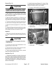
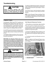
7. If appropriate LED does not toggle on and off when
switch state is changed, check all wiring and connec-
tions to that switch and/or test switch (see Component
Testing in this chapter). Replace anydefective switches
and repair any damaged wiring.
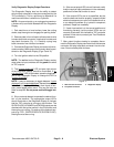
8. After input functions testing is complete, disconnect
the Diagnostic Display connector fromthe harness con-
nector and plug loop back connector into wire harness.
Secure access plate to frame.
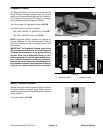
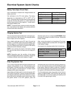
Figure 9
TEC--5002
OVERLAY
(BOTH
GM4500--D
GM4700--D)
AND
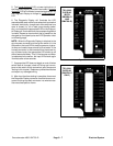
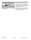
Figure 10
TEC--5001
OVERLAY
(GM4700--D
ONLY)
Electrical
System