


Groundsmaster 4500--D/4700--D Page 6 -- 19 Axles, Planetaries and Brakes
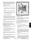
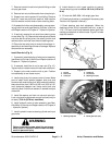
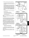
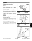
5. Remove the knuckle pin mounting screws and the
knucklepin.Removethe gasketandanyremaininggas-
ket material from either mating surface (Fig. 16).
6. Whileholding thebevel gear case,tapthe upper end
of the bevel gear shaft out of the upper bearing and up-
per bevel gear.
7. Pull the bevel gear case from the axle case and re-
move the upper bevel gear and collar from the gear
case.
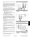
8. Remove the axle case cover screws, cover and the
O-ring from the axle case.
9. Removethe plugandsealing washerfrom thecenter
of the axle case cover. While holding the axle case cov-
er, lightly tap the lower end of the bevel gear shaft out of
the lower bearing and lower bevel gear.
10.Remove and discard bevel gear shaft seal from axle
case (Fig. 16).
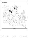
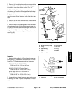
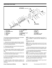
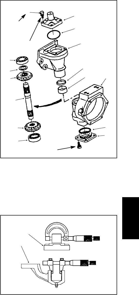
1. Knuckle pin
2. Mounting screw (4 used)
3. O--ring
4. Bevel gear case
5. Upper bearing
6. Bevel gear shaft
7. Collar
8. Upper bevel gear
9. Lower bevel gear
10. Lower bearing
11. Axle case
12. Axle case cover
13. O-ring
14. Shaft seal
15. Bushing
Figure 16
1
2
3
4
5
6
7
8
9
10
11
12
13
14
15
17 to 20 ft--lb
(23to27N--m)
17 to 20 ft--lb
(23to27N--m)
Thread--locking
Compound
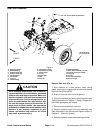
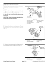
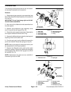
Inspection
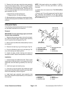
1. Measuretheknuckle pinO.D. andthe axlecase sup-
port bushing I.D. to determine the bushing to pin clear-
ance (Fig. 17). Replace components as necessary.
BUSHING TO PIN CLEARANCE:
0.002 to 0.016 in. (0.05 to 0.40 mm)
KNUCKLE PIN O.D. (Factory Spec.):
0.982 to 0.983 in. (24.95 to 24.98 mm)
AXLE CASE SUPPORT BUSHING I.D.
(Factory Spec.):
0.984 to 0.987 in. (25.00 to 25.08 mm)
2. Inspectall gears,shafts, bearings,cases andcovers
for damage and wear. Replace components as neces-
sary.
1. Knuckle pin 2. Axle case support
Figure 17
1
2
Axles, Planetaries
and Brakes