


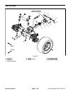

Groundsmaster 4500--D/4700--DHydraulic System Page 4 -- 94
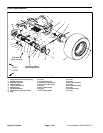
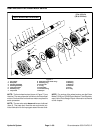
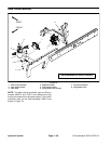
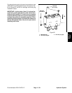
Assembly (Fig. 74)
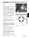
NOTE: When assembling the motor, check the marker
line on each part to make sure the parts are properly
aligned during assembly.
1. LubricateO--rings,pressure seals,back--up gaskets
and wear plategrooves with a thin coat of petroleumjel-
ly. Lubricate all other internal parts freely with clean hy-
draulic oil.
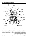
2. Install new seals into front flange (Fig. 76):
A. Press s haft seal into front flange until it reaches
the bottom of the bore.
B. Install flange washer into front flange and then
install retaining ring into the groove of the front
flange.
C. Install new dust seal into front flange.
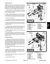
3. Place front flange, seal side down, on a flat surface.
4. Install the pressure seals, flat side outward, into the
grooves in the wear plates. Follow by carefully placing
the backup gaskets, flat side outward, between the
pressure seals and the grooves in the wear plate.
5. Applyalightcoatingofpetroleum jellytotheexposed
side of the front flange.
6. Lubricatethedrivegear shaftwithcleanhydraulicoil.
Insert the drive end of the drive shaft through the wear
platewiththepressureseal sidedownandtheopenside
of the pressure seal pointing to the inlet side of the mo-
tor. Carefully install shaft into front flange.
7. Lubricate the idler gear shaftwith clean hydraulicoil.
Install idler gear shaft into the remaining position in the
front wear plate. Apply a light coating of c lean hydraulic
oil to gear faces.
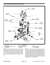
8. Installrear wear platewith pressure sealside up and
open side of the pressure seal pointing to the inlet side
of the motor.
9. Apply a light coating of petroleum jelly to new O--
rings and O--ring grooves in the body. Install new O--
rings to the body.
10.Install locating dowels in body. Align marker line on
the body and front flange.
IMPORTANT: Do not dislodge seals during installa-
tion.
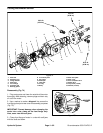
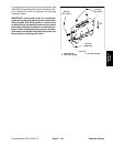
11.Gently slide the body onto the assembly. Firm hand
pressure should be sufficient to engage the dowels.
12.Check to make surethat the surface ofthe rear wear
plate is slightly below the face of the body. If the wear
plate is notbelow thebody,check assembly fora shifted
pressure seal, backup gasket or O--ring. Correct before
proceeding.
13.Apply alightcoatingofpetroleum jellytotheexposed
side of the rear cover.
14.Place rear cover on assembly using marker line for
proper location.Firm handpressure shouldbe sufficient
to engage the dowel pins.
15.Installthe four(4)cap screwswith washersandhand
tighten screws.
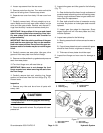
IMPORTANT: Prevent damage when clamping t he
motor into a vise; clamp on the front flange only.
Also, use a vise with soft jaws.
16.Place front flange of the motor into a vise with soft
jaws and alternately torque the cap screws 33 ft--lb (45
N--m).
17.Remove motor from vise.
18.Placea smallamountof cleanhydraulicoilin theinlet
ofthemotorandrotatethedriveshaft awayfromtheinlet
one revolution. If any binding is noted, disassemble the
motor and check for assembly problems.