


Groundsmaster 4500--D/4700--D Page 5 -- 29 Electrical System
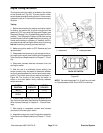
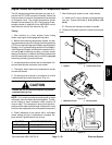
Engine Coolant and Hydraulic Oil Temperature Senders
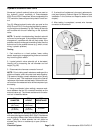
Two (2) identical temperature senders are used as in-
puts for the TEC--5002 controller to identify if either the
enginecoolant orhydraulic oiltemperature hasreached
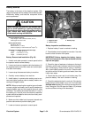
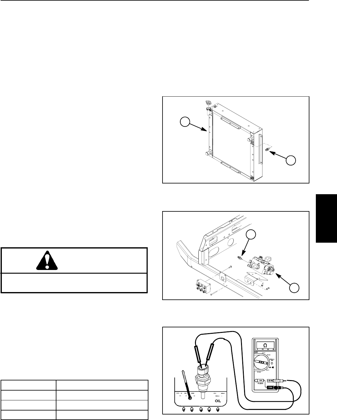
an excessive level. The coolant temperature sender
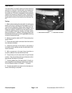
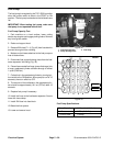
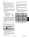
threads into the radiator (Fig.39). The hydraulic oil tem-
perature sender is attached to the 4WD/2WD control
manifold at the front of the machine (Fig. 40).
Testing
1. Park machine on a level surface, lower cutting
decks, stop engine and engage parking brake.
2. Before disconnecting temperature sender for test-
ing, the sender and its circuit wiring should be tested as
a TECinput with theDiagnostic Display (seeDiagnostic
Display in the Troubleshooting section of this chapter).
If theD iagnostic Display verifies that thesender and cir-
cuit wiring are functioning correctly, no further sender
testingisnecessary.If,however,theDisplaydetermines
that the temperature sender and circuit wiring are not
functioning correctly, proceed with test.
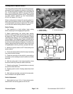
3. Locate temperature sender that is to be tested. Dis-
connect wire harness connector from sender.
4. Thoroughly clean area around temperature sender
and remove sender.
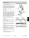
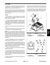
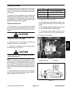
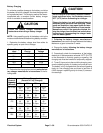
5. Put sensing end of sender in a container of oil with
a thermometer and slowly heat the oil (Fig. 41).
CAUTION
Handle the hot oil with extreme care to prevent
personal injury or fire.
NOTE: Prior to taking resistance readings with a digital
multimeter, short the meter test leads together. The me-
ter will display a small resistance value (usually 0.5
ohms or less). This resistance is due to the internal re-
sistance of the meter and test leads. Subtract this value
from from themeasured value of the testedcomponent.
6. Check resistance of the sender with a multimeter
(ohms setting) as the oil temperature increases. Re-
place sender if specifications are not met.
OIL TEMP
SENDER RESISTANCE
68
o
F(20
o
C) 11.6 to 13.5 ohms
140
o
F(60
o
C) 2.3 to 2.5 ohms
212
o
F (100
o
C) 0.6 to 0.7 ohms
7. After allowing the sender to cool, install sender:
A. Install new O--ring on sender and thread sender
into port. Torque from 9to11ft--lb(12.3to14.9
N--m).
B. Connect wire harness connector to sender.
8. Checkand fillsystem (coolantor hydraulic)toproper
level.
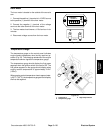
1. Radiator 2. Coolant temp sender
Figure 39
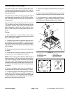
1
2
Figure 40
1. 4WD/2WD manifold 2. Oil temp sender
1
2
Figure 41
Electrical
System